

You are using an out of date browser. It may not display this or other websites correctly.
You should upgrade or use an alternative browser.
You should upgrade or use an alternative browser.
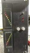
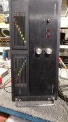
across the bench: an electronic menagerie of diagnostic oddities plus photos and design analysis
- Thread starter sae-7125
- Start date

sae-7125
Super Member
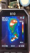
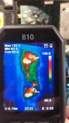
a look behind the heat sink and the axial shish kebab(s).
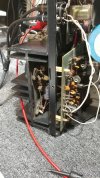
somewhere in there is a bias measurement point.

looks like a 10uf 250v electrolytic is getting roasted with every amplifier performance. there are two per channel sitting on the heat sink or a couple mm above the aluminum griddle. also one 5.6r carbon comp in that area that measures slightly high.
somewhere in there is a bias measurement point.
looks like a 10uf 250v electrolytic is getting roasted with every amplifier performance. there are two per channel sitting on the heat sink or a couple mm above the aluminum griddle. also one 5.6r carbon comp in that area that measures slightly high.
sae-7125
Super Member
there seems to be some troubling details in the citation 16a tech manual that do not exist in the 16 manual, it involves idle heat sink temp and bias voltage.
 www.audioservicemanuals.com
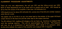
paragraph #3 is literally a smoking gun, 60c/140f idle temp would indicate this amp was trying to be class-a. that would explain why a somewhat low hours amp has 10uf caps measuring 27uf and beyond.
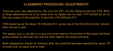
10mv from the 16 manual vs 50mv for 16a, am i missing something here? although turning up the bias beyond 2.5mv (bench citation 16) takes its toll on the mains watt meter. at least the amp boards and relay board are inside the main chamber of the chassis (while a fire/inferno rages in the room next door, if at 10mv bias).
high wattage pull at idle will no doubt heat up the pair of txf's but it will take a while. the large main chamber and mediocre ventilation should help balance what the amp boards are subjected to thermally.
since the amp has not been updated nor recapped yet these preliminary findings might be too much too soon in regards to my usual rant-tastic voyage but it does make a bench monkey think.
Free Audio Service Manuals - Free download harman kardon citation 16 a
Read or download harman kardon citation 16 a PDF with 26 pages. No login, no charge and no limit.
www.audioservicemanuals.com
paragraph #3 is literally a smoking gun, 60c/140f idle temp would indicate this amp was trying to be class-a. that would explain why a somewhat low hours amp has 10uf caps measuring 27uf and beyond.
10mv from the 16 manual vs 50mv for 16a, am i missing something here? although turning up the bias beyond 2.5mv (bench citation 16) takes its toll on the mains watt meter. at least the amp boards and relay board are inside the main chamber of the chassis (while a fire/inferno rages in the room next door, if at 10mv bias).
high wattage pull at idle will no doubt heat up the pair of txf's but it will take a while. the large main chamber and mediocre ventilation should help balance what the amp boards are subjected to thermally.
since the amp has not been updated nor recapped yet these preliminary findings might be too much too soon in regards to my usual rant-tastic voyage but it does make a bench monkey think.
sae-7125
Super Member
input audio chip seems to have a mechanical mod from the factory.
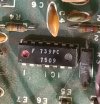
fairchild ua739 with pin 5 clipped off.

floating the pin to whatever noise is in the area seems like an odd design strategy.

pin 5 also being an input that may impact the rest of the circuit. wonder if this was a contributing factor for the 16a input redesign.
fairchild ua739 with pin 5 clipped off.
floating the pin to whatever noise is in the area seems like an odd design strategy.
pin 5 also being an input that may impact the rest of the circuit. wonder if this was a contributing factor for the 16a input redesign.
sae-7125
Super Member
revised thermals (no bulb) and bias vs mains wattage.

right channel.
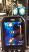
relay board plus half of right and left channels. i seem to have neglected to do a full left channel shot, oops.

2.0mv bias as a point of reference vs 10mv in the manual.
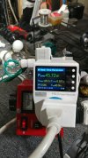
green wire connected to switch is bulb bypass for the dim-franken-bulb-stein apparatus, its weird i know.
i should probably do a curve ball post next vs droning on about a sweet sixteen citation from long ago. oddly enough txf surface rust seems to be more common on these than i had thought.
right channel.
relay board plus half of right and left channels. i seem to have neglected to do a full left channel shot, oops.
2.0mv bias as a point of reference vs 10mv in the manual.
green wire connected to switch is bulb bypass for the dim-franken-bulb-stein apparatus, its weird i know.
i should probably do a curve ball post next vs droning on about a sweet sixteen citation from long ago. oddly enough txf surface rust seems to be more common on these than i had thought.
sae-7125
Super Member
how about a carver m-400t, carver cube.
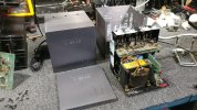
almost fits in the palm of your hand.
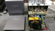
lots of screws to disassemble this little monster.

rear metal support where all the outputs are mounted is covered in thermal paste.

speaker terminals could use an upgrade plus the usual recap.
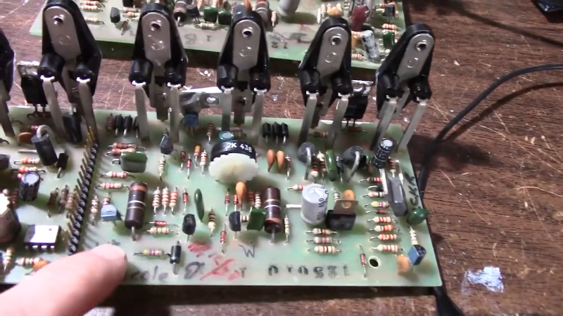
 hackaday.com
*comments section full of interesting info.
hackaday.com
*comments section full of interesting info.
almost fits in the palm of your hand.
lots of screws to disassemble this little monster.
rear metal support where all the outputs are mounted is covered in thermal paste.
speaker terminals could use an upgrade plus the usual recap.
Carver M-400 Amplifier Repair Keeps The 1980’s Alive
Carver is a famous name in audio equipment although they have been known to use odd names for things. For example, the 1980’s vintage M-400 magnetic field power amplifier that [JohnAudioTech]…
hackaday.com
sae-7125
Super Member

not much breathing room for the output transistors.
sae-7125
Super Member
few more shots of the cube, technically this amp predates the borg from the delta quadrant.

 memory-alpha.fandom.com
if the face plate is the bow and the power transistors are stern than this would be the port side.
top board, amidships, with output device sockets aft.
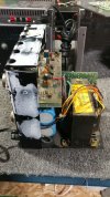
starboard side has a nice view of the largest power caps, since this design has rail stepping voltages.
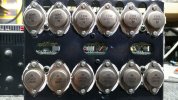
closer look at output numbers: motorola c4000, c5000, c10000, c11000
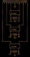
block diagram from the service manual.
 www.diyaudio.com
www.diyaudio.com

 www.youtube.com
*and for those interested in nautical related news.
www.youtube.com
*and for those interested in nautical related news.
Delta Quadrant
The Delta Quadrant was the common designation for one-quarter of the Milky Way Galaxy. This quadrant was adjacent to the Beta Quadrant and to the Gamma Quadrant. The quadrant's closest point to the United Federation of Planets was located in the galactic core, which was located approximately...
memory-alpha.fandom.com
if the face plate is the bow and the power transistors are stern than this would be the port side.
top board, amidships, with output device sockets aft.
starboard side has a nice view of the largest power caps, since this design has rail stepping voltages.
closer look at output numbers: motorola c4000, c5000, c10000, c11000
block diagram from the service manual.
Is there a better transistor than a Motorola C4000/C5000
The C4000/5000 set in my Carver M200t seems to have seen better days. Now I have got MJ15001/2 and MJ15024/5 that are direct swaps. However I am planning on re jiggering the heat sink and get the transitors to go flat onto another panel. So I'm thinking I can drop in a different transistor...
Carver cube distorted output
Hi guys! I might be in a little too deep this time. I've got a carver m400t with a heavy distorted left channel. I know 1 output is shorted. It is marked C4000. I can't find any info on what it crosses to. Nor do I know for sure that it is my only problem. Anyone familiar with these?
What is Going on With Shipping?
What's Going on With Shipping focuses on Maritime Industry Policy, and current events in the Maritime Sector, along with Maritime History. The channel features videos that examine the world's merchant marines, the international maritime sector, current events in the maritime trade, and...
www.youtube.com
sae-7125
Super Member
back to the citation sixteen and its LED display boards.
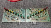
some electrolytics and carbon comps need to be updated.

solder joints look a bit thin over the entire LED board. increasing the chances of...
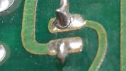
having broken solder joints.
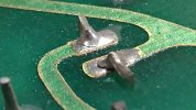
in more than one place/component. amp boards will also need to be inspected closely plus the relay board.
some electrolytics and carbon comps need to be updated.
solder joints look a bit thin over the entire LED board. increasing the chances of...
having broken solder joints.
in more than one place/component. amp boards will also need to be inspected closely plus the relay board.
sae-7125
Super Member
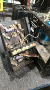
beyond the amp board and into the oven/heat sink domain.
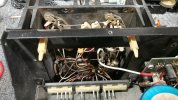
amp boards are relatively easy to remove and service without having to remove the heat sink.
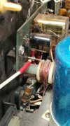
relay board is a different story. oh look more carbon comp resistors.
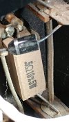
close up of one of the many emitter resistors on the heat sink plus a diode.
amp boards are relatively easy to remove and service without having to remove the heat sink.
relay board is a different story. oh look more carbon comp resistors.
close up of one of the many emitter resistors on the heat sink plus a diode.


sae-7125
Super Member
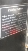
indeed it is, a time capsule of information that has withstood the test of time, and who knows how many crazy parties. they picked a location that protects it, the sticker, from the usual forms of physical wear when moving the amp.That sticker is cool!
i wonder how many of the engineers listed are still in attendance on planet earth these days, above ground.
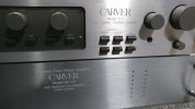

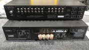

Very good stuff indeed.
I remember wanting one of the lil cube amps!
But was told they are difficult to work on, and much easier to WOK on as they run hot..
enough humor , as I am now figuring out my IPad… yeeesh like I needed something new to learn.
My best…
Carry on in the great fashion that you do!
Learning to type again, guess I need longer fingernails… something only time will accomplish.
I remember wanting one of the lil cube amps!
But was told they are difficult to work on, and much easier to WOK on as they run hot..
enough humor , as I am now figuring out my IPad… yeeesh like I needed something new to learn.
My best…
Carry on in the great fashion that you do!
Learning to type again, guess I need longer fingernails… something only time will accomplish.
sae-7125
Super Member
some of the carver amps can be tricky since we are not talking about class-a or class-ab with bobs designs.But was told they are difficult to work on
sae-7125
Super Member
inside the c-1 preamp.
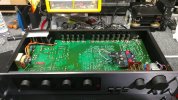
although this is the bottom of the board there are some important upgrades installed by nelionaudio.com (greg).
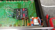
the preamp now has remote control for volume as well.
fyi: bob carver helped greg to create nelion audio.
although this is the bottom of the board there are some important upgrades installed by nelionaudio.com (greg).
the preamp now has remote control for volume as well.
Carver C-1/C-11 Restore and Bill D Upgrades
Take your Carver C-1 preamplifier to better than new state with the BillD mod from Nelion Audio, a Carver authorized, Bob Carver recommended repair and restoration shop.
nelionaudio.com
fyi: bob carver helped greg to create nelion audio.