• The move to the new server is done. There are some software and database maintenance updates in process. This has us passing the hat around to help out. We appreciate any donations. Seriously, even a dollar helps. The payment page may be found here - https://www.audiokarma.org/support.html

across the bench: an electronic menagerie of diagnostic oddities plus photos and design analysis

testing some speakers (near field) before they go out to the demo chamber.

paradigm 200b - 1.jpg
rather odd design choice to have the woof and tweeter completely covered with a plastic grill that has a great many holes.

paradigm 200b - 2.jpg
paradigm premier 200b bookshelf speakers.


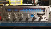
evaluating a marantz 2238b, a few age related circuit issues.


mar 2238b - 1.jpg
speaker selector quirk just needed a face plate realignment. the four bolts were suspiciously loose.

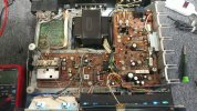
mar 2238b - 2.jpg
boards have some dust accumulation but nothing major.

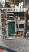
mar 2238b - 3.jpg
left channel dc offset circuit needs work and some issues when trying to set the power supply pot. this will need more than a recap.


major differences between 2238b and the 2238:

 
more photos of the 2238b and the usual design critique.

mar 2238b - 4.jpg
power caps located under the boards... and directly next to the heat sink for the output transistors... seriously? since heat rises it shouldnt be too much of an issue but they could have figured out something better.

mar 2238b - 5.jpg
a small pocket of space for the caps, not many mounting options for this type of layout.

if the dc bias is set slightly lower (19 vs 23mv, steely dan "hey nineteen") and if the owner doesnt thrash the amp on a regular basis (earth, wind & fire "lets groove" + bass turned up) the power cap closest to the heat sink should survive for a reasonable service lifespan. although this is just a wild and crazy guess with insufficient data to support any claim either way, tuner discretion is advised.

although if high ripple current is the norm, the caps will cook from the inside out over time.
 
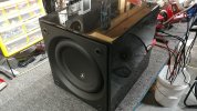
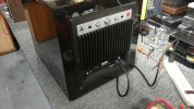
testing a powered sub before it goes into the showroom to massage the ceiling tiles and windows.

jl d110 - 1.jpg
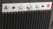
JL audio with a healthy sized surround on the subwoofer.

jl d110 - 2.jpg
nice amount of controls to dial in low frequency ability.

jl d110 - 3.jpg
JL audio d110 has some heft when lifting it onto the bench.

 
marantz 2215b receiver ready for action after doing some basic testing.

mar 2215b - 1.jpg
chassis in decent condition.

mar 2215b - 2.jpg
cosmetics seem to have survived the test of time.

mar 2215b - 3.jpg
speaker terminals would benefit from some banana adapters although this is a low wattage system (fire hose speaker cables optional).


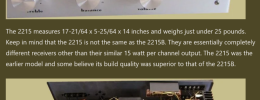
quick comparison of 2215b vs 2215:

Screenshot 2024-08-21 at 10-54-35 Marantz 2215 Classic Receivers.png
 
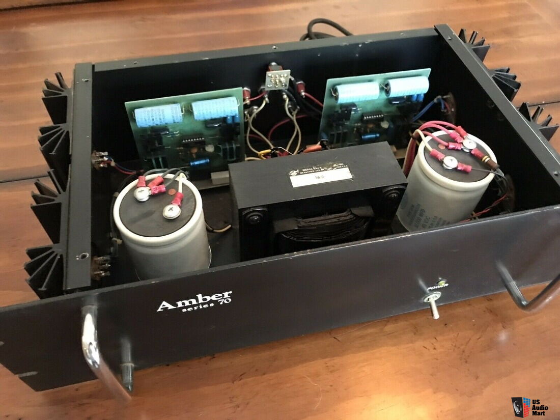
looks like an amber series 70 power amp might be the next diagnostic migraine to contend with, "one channel makes a bad noise" is the complaint.

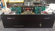
amber s70 - 01.jpg
black face plate seems to be of significance in regard to version, with difficulty finding an accurate schematic at this point in time.

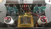
amber s70 - 02.jpg
not exactly terrible to work on but each channel will take some time to remove and maneuver somewhat to make desoldering a double sided board possible. without causing damage to the through-hole design.

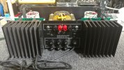
amber s70 - 03.jpg
amp can be bridged into mono and has more than a few fuses that might protect it from meltdown or abuse, havent evaluated fuse size vs circuit function yet.

this project may end up consuming the rest of this thread page with diagnostic methodology and reference material from various internet sources. the same could be said of the recent conrad johnson pv5 tube preamp depending on how far the owner wants to repair/enhance it.

amber s70 - 04.jpg
both amp boards have LM391N-100 chips and who knows how long this ran at the factory bias of 150ma. a few posts on the net talk about 40-50ma being the safe/recommended bias setting since the heat sinks and emitter resistors are not ideal for class-a operation.

the quantum gremlin hunt begins, mechanics license optional.


the amplifier circuit design looks like it was copied and pasted from the "application hints" schematics from the LM391 spec sheet. with minor adjustments and deletions, i guess everybody has to start there business from something and service bulletin it until the next model is ready.
classic vintage trial and error engineering that continues to this day.

Screenshot 2024-08-21 at 18-39-54 LM391 Audio Power Driver - LM391N-100.pdf.png
the complications of relying on one chip to do many things. and when that special chip is no longer manufactured things get interesting.
 
electrolytic quality control issue, possibly the cap manufacturer or...

amber s70 - 06.jpg
if the cap was damaged at the amp factory during assembly? no idea if amber had their boards built/soldered in another country. note, carbon comp north of the physically damaged cap.

amber s70 - 07.jpg
a few carbon comp resistors inside the chassis (1 per amp board), LED circuit not a big deal when the carbon comp gradually increases resistance over time.
 
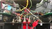
resistor connecting rca input negative to speaker negative which is connected to chassis ground (green wire star pattern).
amber s70 - 05.jpg
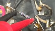
odd to see a notable value resistor between the measurement points. but this may explain why i was measuring 37v dc across the outputs terminals. a slight residual voltage if there is no grounding resistor or something. bridging switch was set to stereo mode, first thing i looked at after seeing the high voltage dc offset (no speaker load, no signal source connected). might be fusible resistors, wonder why/how both are dead now (meg-ohm and beyond, in circuit).
amber s70 - 08.jpg
brown black black gold brown, lets get a second opinion on what that should be. these resistors are not mentioned in any service bulletin.

amber s70 - 09.jpg
calculator says: 10r 1%

*several sites with calculators, another example.

so the first electrical anomaly found was the dc offset red flag event when powering up the amp for the first time on the bench, 40+40w bulb active. after soldering a pair of fresh 10r resistors in parallel with originals (quick tack weld for diagnostic purposes) the next thing was watching the kilowatt meter on my hack-job dim bulb tester. it was 19w with the open resistors and then went to 40w (dbt safety net restricted) after the fix.

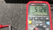
after probing around with the dmm i noticed the idle wattage drop down to around 25w. what changed? actually nothing, eventually it was noticed that touching the right channel (spoiler alert, channel with the noise found) input positive causes the dc bias to drop and the idle wattage with it. hello high kilohertz oscillation, dmm measured around 867khz (dmm) at around 850mv ac on the naughty channel output (right channel) when the dbt is glowing.

the entire amp board is original. no signs of previous work although the surface of the pcb has various scratches from the assembly process at amber, or something. freeze spray did not help locate any specific component or sensitive region of the amp board.

the investigation continues.

 
oscillation measurements.

amber s70 - 10.jpg
briefly removed the LM391 for inspection, should do some resistance measurements while its out (chip and socket) and compare the channels.

amber s70 - 11.jpg
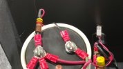
measuring 684.2khz on the output when the bias spikes. the 867khz mentioned earlier was incorrect, bad memory on my part.
amber s70 - 12.jpg
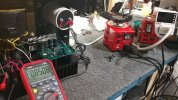
at least i remembered this voltage correctly, dim bulb glowing as a reminder of things going wrong.
 
Interesting amp that Amber.
Kudos to you for taking on a repair like that...

Looks like from one of the posts you linked, Amber went BK ...
I guess that may be better than being Corporate gobbled up...
 
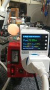
kilowatt meter numbers.

amber s70 - 13.jpg
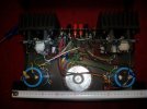
when the bias spikes due to an unknown sensitivity somewhere.
amber s70 - 14.jpg
vs a normal looking idle although both channels have their bias pots turned down. point of reference is measuring voltage between positive speaker output and the collector of each output transistor (easy to access soldered lead on the board). this type of bias measurement is different than what is specified in the service bulletin.

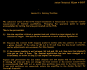
Screenshot 2024-08-22 at 16-41-44 amber_series_70_service_bulletins.pdf.png
post #348 above specifies why setting to 150ma is a bad idea and how 40-50ma is the correct value.

there are two uniquely different chassis/heat sink designs for the series 70. judging by surface area, the other chassis might handle higher heat/bias levels better.

*an example of the other design.
 
disassembling the right channel.

amber s70 - 15.jpg
four screws hiding between the sink fins plus removing the nylon hardware that mounts the driver transistors plus mini heat sink subassembly.

amber s70 - 16.jpg
pcb version numbers or something.

amber s70 - 17.jpg
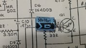
c10 in the board doesnt exactly line up with whats on this version of the schematic.
 
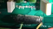
r19 and c10 circuit location.

amber s70 - 18.jpg
after removing c10 i noticed r19's location and value vs the schematic.

amber s70 - 19.jpg
i wonder if most of the q5 circuit was deleted during the chassis heat sink revision.
 
starting the recap and overhaul of the amp board.

amber s70 - 20.jpg
the big electrolytics have polarity silkscreened on the board.

amber s70 - 21.jpg
starting to take shape even though a few more components will be updated. oscillation still present (after recap) when the circuit is stimulated via the right channel positive speaker output. this channel loves 680khz for some odd reason, must be the circuit equivalent to catnip or something.
 
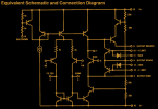
spec sheet: equivalent schematic and connection diagram, and how it is beyond inaccurate.

amber s70 - 22.jpg
measuring across pins 8 an 9.

amber s70 - 23.jpg
pins 8 and 16.

amber s70 - 24.jpg
pins 9 and 16.

amber s70 - 25.jpg
pins 15 and 16.

comparing these measurements to the spec sheet and its "equivalent" claim, more than a few things dont add up. as if a dud schematic wasnt enough now the dud spec sheet is suspect. comparing left channel and right channel chips show slightly lower internal resistances. right channel aged more or is falling out of tolerance quicker and yet still reasonably functional.

Screenshot 2024-08-21 at 18-39-54 LM391 Audio Power Driver - LM391N-100.pdf.png
revisiting what should be measured and where. 14&15 = 10k, 9&15 = 50k, 9&16 = 50k. 15&16 = 100k. if only this were true.

moving forward, at least the chips are not an issue from a functionality stand point. replacing with new-old-stock would be difficult. ebay shows 100% china sources, high probability of fakes or rebadged junk. there seems to be more than a few oddities about the amp board circuit design and factory implementation. chopped traces and a resistor connected to nothing... did the bean counters get a hold of this product design or was there an engineering rebuttal in progress in a rebellious fashion.

yet another diagnostic denouement.
 
a few more thoughts about the chip.

amber s70 - 26.jpg
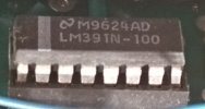
obviously national semiconductor is the brand. the m9624ad could be a manufacturing code.


an interesting thought, when did the silkscreen logo change on the 16pin dips for national semiconductor? from the older two wavy lines stacked vs the somewhat newer rounded "N". looking through databooks and catalogs i have yet to find an LM391 datasheet prior to 1994. the older version might have a more accurate "equivalent schematic" even though this is not a high priority nor mission critical amount of data.

there must be yet another version of the amber schematic for the earlier dual card version.

amber-series-70-amplifier cards.jpg
one pair of large electrolytics per card vs two pair on the schematic. how does anyone get any type of diagnostic work done on these things. yes, it is a very simple layout and a handful of parts per card.

*photo source.

slowly nearing the end of the diagnostic journey.
 
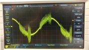
the not so great waveform output of the right channel.

amber s70 - 27.jpg
something looks a bit unhealthy with this 63hz sinewave, signal out from dac into the amp inputs.

amber s70 - 28.jpg
simple scope measurement (floating ground) across the output with speakers attached.

amber s70 - 29.jpg
not much heat generated at idle although still on the 40+40w dim bulb. i should have reduced the temp scale down from 185 max.

amber s70 - 30.jpg
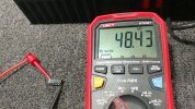
bulb greatly reduces the rails and the zener diode activity. normally 39.5v for the zener regulator and 42-43v for each rail. power caps rated for 45v, not much room for safety.
 
Back
Top Bottom