You are using an out of date browser. It may not display this or other websites correctly.
You should upgrade or use an alternative browser.
You should upgrade or use an alternative browser.
across the bench: an electronic menagerie of diagnostic oddities plus photos and design analysis
- Thread starter sae-7125
- Start date


There is or at least was a Pass forum that Nelson P would participate in, some of those guys were way into "Papa Zen's" products ... give me a bit and I shall see if I can find if its around.
Of course, here it is; it's a sub of diyAudio.
Pass Audio Forum
Of course, here it is; it's a sub of diyAudio.
Pass Audio Forum

sae-7125
Super Member
after looking at my post above and how poorly worded the voltages are perhaps i should clear up a few things. before i confuse myself and anyone that might bump into page 17 of this lengthy thread.
+/- referring to the upper and lower rail voltages, independently, which is incorrect when stating the total voltage across both caps at the same time. i should have stated +/- 41v per rail or 82v total rail-to-rail. pardon my epic brain-fart for the initial "misleading" measurements in post #321... contact, then cue comedic explosion similar to what was portrayed in the 2009 movie "fantastic mr. fox". boggus bunce and bean were some interesting villains plus the voice acting was quite enjoyable. even more so if utilizing a class-a amplifier and your favorite speakers.
this amp must be one of the rare designs where power filter caps are "noticeably" over-sized from a voltage stand point i.e. 100v cap that is subjected to less than 50v during normal operation. nicely done mr. pass.
+/- referring to the upper and lower rail voltages, independently, which is incorrect when stating the total voltage across both caps at the same time. i should have stated +/- 41v per rail or 82v total rail-to-rail. pardon my epic brain-fart for the initial "misleading" measurements in post #321... contact, then cue comedic explosion similar to what was portrayed in the 2009 movie "fantastic mr. fox". boggus bunce and bean were some interesting villains plus the voice acting was quite enjoyable. even more so if utilizing a class-a amplifier and your favorite speakers.
this amp must be one of the rare designs where power filter caps are "noticeably" over-sized from a voltage stand point i.e. 100v cap that is subjected to less than 50v during normal operation. nicely done mr. pass.
sae-7125
Super Member
Forte Model 4 ( Power Supply upgrade)
Hi, I need some advice on upgrading the power supply on my Forte Model 4 amplifier. In case you are not farmiliar with this design it is 50W Class A using the IGBT devices. There are 4 main caps and 2 bridges. The stock caps are rated at 100V 15,000uF each. Is 100V rating really necessary...
Forte model 4 article
I just purchased a forte model f-44 preamp and the guy i bought it from also included an article on the forte model 4 amp plus some info about it in the brochure that i thought i'd share with you guys.
Search results for query: forte model bias
Forte 4 Power Amp, Info?
I need some more information about the Forte4 power amp. Possibly where to find replacement parts, So Once again I come to the forum, Is there a conversion kit to change the multi - voltage input or a Replacement cam that I can buy , I am also wondering, why the Big electrolytic capacitors are...
havent found anything yet on diyaudio, the hunt continues. luckily the model 4a on the bench doesnt have any catastrophic issues to diagnose. its interesting to note that nelson was not very fond of the igbt audio design. earlier generations were quite limited but sufficient for motor control applications. the newer generations available today have conquered a few barriers and thats before we get into gallium nitride tech.

SiC and GaN vs. IGBTs: The Imminent Tug of War for Supremacy
Automotive, industrial, and other applications that require smaller size, lighter weight, and more efficient operation are increasingly looking to SiC and GaN solutions.
 www.electronicdesign.com

SiC and GaN - a power walkthrough
With most industries increasing their focus on energy efficiency, both Silicon Carbide and Gallium Nitride are gaining ground in power devices. This article will cover the basics of these materials.
 siliconmatter.substack.com
sae-7125
Super Member
a few more forte photos and idle wattage.

looks like an older "monster cable" logo wire being used for chassis connections. i tend to avoid that particular brand as much as possible but everybody is different with their preference of electrical conductors.

rear panel wiring zip tied (factory) to keep it away from power wires or other sources of noise injection.
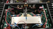
overall interior photo, front to back and the large aluminum buss bar being used as a central ground connection (wonder if copper would sound better). many zip ties self-destructed due to heat exposure which should give an idea as to how many hours are on the amp.

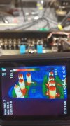
idle wattage, no bulb. there was a thermal imbalance between the two channels, left hotter than right at idle (~15f variance), which was easily corrected when adjusting the hotter channel to a lower bias setting. nice to see a pair of pots per channel, newer fully sealed plastic housing.
looks like an older "monster cable" logo wire being used for chassis connections. i tend to avoid that particular brand as much as possible but everybody is different with their preference of electrical conductors.
rear panel wiring zip tied (factory) to keep it away from power wires or other sources of noise injection.
overall interior photo, front to back and the large aluminum buss bar being used as a central ground connection (wonder if copper would sound better). many zip ties self-destructed due to heat exposure which should give an idea as to how many hours are on the amp.
idle wattage, no bulb. there was a thermal imbalance between the two channels, left hotter than right at idle (~15f variance), which was easily corrected when adjusting the hotter channel to a lower bias setting. nice to see a pair of pots per channel, newer fully sealed plastic housing.
sae-7125
Super Member
the left channel noise situation.

rca/unbalanced input measurement.
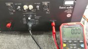
XLR/balanced input measurement. the right channel is 0v for both rca and XLR.
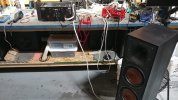
using a 97db efficient speaker to evaluate how loud the "noise" situation is.
the forte would benefit from a recap, obviously, but anything more in depth (without schematic) could be difficult. to access each channel pcb it requires a complete disassembly to access the plated through-hole boards. plus removing the boards from their heat sinks which requires unbolting all the outputs.
rca/unbalanced input measurement.
XLR/balanced input measurement. the right channel is 0v for both rca and XLR.
using a 97db efficient speaker to evaluate how loud the "noise" situation is.
the forte would benefit from a recap, obviously, but anything more in depth (without schematic) could be difficult. to access each channel pcb it requires a complete disassembly to access the plated through-hole boards. plus removing the boards from their heat sinks which requires unbolting all the outputs.

sae-7125
Super Member
the rack mountable sansui au-717 that was mentioned earlier.
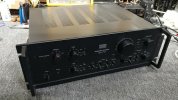
looks like it is in decent cosmetic condition.
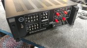
and it had a banana upgrade before there were any cap upgrades.

under the hood looks original, going to need more than a few updates plus one channel is down, which is why its at the repair shop.
 hifi-wiki.com
 www.audioservicemanuals.com
*looks like photobucket did its usual damage to some of the photos.
looks like it is in decent cosmetic condition.
and it had a banana upgrade before there were any cap upgrades.
under the hood looks original, going to need more than a few updates plus one channel is down, which is why its at the repair shop.
Sansui AU-717 | hifi-wiki.com
Free Audio Service Manuals - Free download Sansui AU 717 Owners Manual
Read or download Sansui AU 717 Owners Manual PDF with 58 pages. No login, no charge and no limit.
www.audioservicemanuals.com
Leestereo's Restoration/Upgrade Of A Sansui AU-717
A very nice Sansui AU-717 was on the workbench for a complete restoration and upgrade. The restoration/upgrade plan included the following: 1. Replace all power supply electrolytic capacitors with low ESR types (increasing capacity where appropriate and physically possible). 2. Replace all of...
audiokarma.org
sae-7125
Super Member
excellent question, i will add that to the diagnostic list for today.What happens to the voltage if you short the RCA input?
if i remember correctly, when a source is connected (no active signal) the noise/voltage continues to exist. something else that i will have to double/triple check when at the bench.
sae-7125
Super Member
more photo notes of the igbt forte model 4a.

with a source connected the output noise floor on both channels is consistently around 0.6mv rca and 0.45v XLR. shorting the rca input is no different than clicking the switch to XLR input in that a low input impedance is activated (300r XLR vs 0.0r shorted) which is more than an order of magnitude less than 50k for rca input.
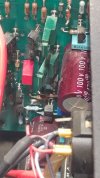
stabilizing the left channel seemed to happen after mechanically adjusting some of the large transistors on the amp board plus rerouting some of the chassis wiring. prior to the bending of components i noticed a proximity reactance. in addition to when blowing air across some of the input circuitry the output noise floor reacted noticeably. chances are there are more than just a few thermally aged components, ic on that end as well.
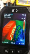
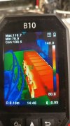
thermally balanced the two channels within 0.5f at idle (right channel above), that should be somewhat tolerable for the demo chamber testing.
left channel above (initial problem child).
with a source connected the output noise floor on both channels is consistently around 0.6mv rca and 0.45v XLR. shorting the rca input is no different than clicking the switch to XLR input in that a low input impedance is activated (300r XLR vs 0.0r shorted) which is more than an order of magnitude less than 50k for rca input.
stabilizing the left channel seemed to happen after mechanically adjusting some of the large transistors on the amp board plus rerouting some of the chassis wiring. prior to the bending of components i noticed a proximity reactance. in addition to when blowing air across some of the input circuitry the output noise floor reacted noticeably. chances are there are more than just a few thermally aged components, ic on that end as well.
thermally balanced the two channels within 0.5f at idle (right channel above), that should be somewhat tolerable for the demo chamber testing.
left channel above (initial problem child).

Pio1980
AK Member
Was this by Jim Bongiorno?here is the little monster that instigated the creation of an ak account:
View attachment 3223067
brain surgery of the gorler tuning gang for the sae monster. replaced several components, soldering two grains of sand together would have been easier.
View attachment 3223071
the monster aka sae mark vi (a) nixie tuner, fully functional now. i high-jacked another persons thread with the investigative details (nixie board chips).
View attachment 3223072
sae super stack , as i refer to it, the gang is back in action and together again (ready to rock), shopping for new vu meters was interesting but functional.
sae-7125
Super Member
it is possible, judging from an interview where he said:Was this by Jim Bongiorno?
"SAE was founded by Morris Kessler and Ted Winchester in around 1969. They were never a happy couple however. After a while, Morris bought out Ted's interest. I was originally hired to replace Ed Miller doing tuner design. But Morris was immediately made to realize (by me of course) that he was NOT an engineer and therefore, I would not stay at SAE unless he removed himself from engineering. He had no choice as I said to him "take it or leave it". Morris acquiesced and for the next couple of years I designed all the products."

About SST-High-end amplifiers and High-end audio — SST
High-end amplifiers High-end audio
 www.sst.audio
sae-7125
Super Member
testing the forte in the demo chamber, pardon the mess of "other" audio equipment in attendance.

using a variac to dial in 120v exact on the mains for the forte amp. it feeds a pair of 97db efficient klipsch speakers, sorry no corner horns readily available (they still need refurb in the warehouse area). using bluesound streamer to feed schiit modius dac (coax input) and then into an audio research model sp20 tube preamp. rca/unbalanced used for the entire analog circuit chain of devices.
 www.arcdb.ws
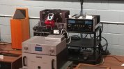
a closer look, try not to be distracted by the audio research vt100 mk3 tube amp under the preamp.
www.arcdb.ws
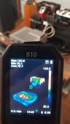
tube preamp plus class-a solid state amp thermally active, check, and ready for some demo tunes.
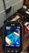
forte amp seems to be firing on all cylinders, compound turbo running 30 pounds of boost (maybe if it was an ALH 1.9L diesel).
 forums.tdiclub.com
using a variac to dial in 120v exact on the mains for the forte amp. it feeds a pair of 97db efficient klipsch speakers, sorry no corner horns readily available (they still need refurb in the warehouse area). using bluesound streamer to feed schiit modius dac (coax input) and then into an audio research model sp20 tube preamp. rca/unbalanced used for the entire analog circuit chain of devices.

ARCDB
The Audio Research Database (ARCDB) provides information about past and present products from ARC (Audio Research Corporation)
a closer look, try not to be distracted by the audio research vt100 mk3 tube amp under the preamp.
ARCDB
The Audio Research Database (ARCDB) provides information about past and present products from ARC (Audio Research Corporation)
tube preamp plus class-a solid state amp thermally active, check, and ready for some demo tunes.
forte amp seems to be firing on all cylinders, compound turbo running 30 pounds of boost (maybe if it was an ALH 1.9L diesel).
Maximum Boost from Turbo For a stock 1.9 TDI motor
I was wondering what the Maximum Boost you should use for a 1.9TDI motor is? So if i upgrade one day I know what I can look into
forums.tdiclub.com
sae-7125
Super Member
final numbers for the thermal balancing of the forte.

122.9f for left channel, originally had some noise issues. system has not been recapped so far.
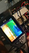
123.8f right channel.
thermals above taken after thrashing the amp for an hour and monitoring wattage peaks at the mains.
running XLR from dac to preamp and preamp to amp would have decreased perceived noise floor but thats not a testing option when a person has zero XLR cables on hand. i really need to do something about that one of these days.
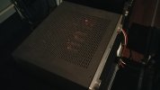
since the amp was tested with the top plate removed this is not thermally accurate for the average/normal user. a slight variance is to be expected especially after the full chassis gets heat soaked and begins reflecting what it absorbed. this amp is still considerably cooler, temp wise, than a conrad johnson pv5 tube preamp. which there seems to be one sitting on the inbox shelf recently.
122.9f for left channel, originally had some noise issues. system has not been recapped so far.
123.8f right channel.
thermals above taken after thrashing the amp for an hour and monitoring wattage peaks at the mains.
running XLR from dac to preamp and preamp to amp would have decreased perceived noise floor but thats not a testing option when a person has zero XLR cables on hand. i really need to do something about that one of these days.
since the amp was tested with the top plate removed this is not thermally accurate for the average/normal user. a slight variance is to be expected especially after the full chassis gets heat soaked and begins reflecting what it absorbed. this amp is still considerably cooler, temp wise, than a conrad johnson pv5 tube preamp. which there seems to be one sitting on the inbox shelf recently.


sae-7125
Super Member
conrad johnson pv5 tube preamp with phono, mentioned earlier, that is now being inspected and diagnosed for a quote.
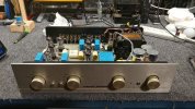
this one has low hours and is not burnt to a crisp like the previous pv5 from a year ago.
*researching mlcc vs electrolytic for potential modz.

this one has low hours and is not burnt to a crisp like the previous pv5 from a year ago.
*researching mlcc vs electrolytic for potential modz.