• The move to the new server is done. There are some software and database maintenance updates in process. This has us passing the hat around to help out. We appreciate any donations. Seriously, even a dollar helps. The payment page may be found here - https://www.audiokarma.org/support.html

across the bench: an electronic menagerie of diagnostic oddities plus photos and design analysis

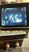
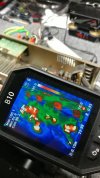
some thermals of the crown.

crown dc300 - 8.jpg
main board is the only thing that gets warm unless stress testing the outputs.

crown dc300 - 9.jpg
different color scheme.

crown dc300 - 10.jpg
idle wattage with 200w big bulb + 40w small bulb on the latest dbt version.
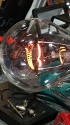
crown dc300 - 11.jpg
playing some music to exercise the high wattage filament.

since the amp is class a/b +b its output stage gets upset when loaded (speakers connected) and using a reasonable size bulb (40+40+40). power up the amp unloaded or with one speaker isnt too bad when doing safe testing of the system, initial diagnostics.

the sae amp in the past reacted the same way and was also class-b, if i remember correctly.
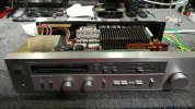
 
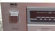
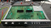
mcs 3842 integrated amp, small with a rather large heat management system.

mcs 3842 - 1.jpg
basic cosmetics and what could be a nice looking display. just one problem that will be apparent soon.

mcs 3842 - 2.jpg
modular component systems.

mcs 3842 - 3.jpg
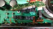
gremlin hint:
 
final batch for the mcs.

mcs 3842 - 4.jpg
note the txf has been unbolted from the frame. easier to inspect and measure the primary + secondary windings.

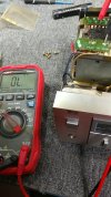
mcs 3842 - 5.jpg
measuring across the primary and it is open. that would explain zero voltage on the secondary and dc supply.

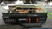
mcs 3842 - 6.jpg
rear panel photo and the txf has been bolted down to its normal position. trying to source a replacement txf exceeds the repair budget so this will most likely be headed to the recycle pile, depending on what the owner decides.
 
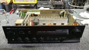
yamaha natural sound stereo amplifier, with an issue that will need specialized surgery.

yam 500 - 1.jpg
another relatively small integrated, output transistors have decent spacing plus lots of heat dissipation surface area around them.

yam 500 - 2.jpg
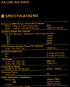
yamaha ax-500u

yam 500 - 3.jpg
the preamp output jumpers will receive some deoxit gold attention.

yam 500 - 4.jpg
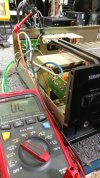
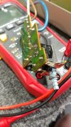
and the hunt begins, time to corner the gremlin for extraction. in this case identifying a power switch issue. button clicked into "on" position and no conductivity. a simple "cord to the board" diagnostic procedure.


A shame about that little MCS and its dead power tranny - looks like a cool little amp.
 
more yamaha power switch info.

yam 500 - 5.jpg
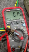
when pushing the button to its max inward position we have conduction.

yam 500 - 6.jpg
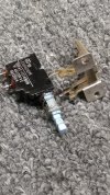
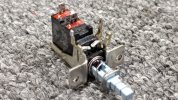
power switch removed from its board, which requires removing the entire face plate.

yam 500 - 8.jpg
and now we delve into the heart of the matter. the usual spray made no improvements, just made a larger mess when extracting the mechanism.

more surgery photos to follow.
 

Attachments

  • yam 500 - 7.jpg
    yam 500 - 7.jpg
    130.1 KB · Views: 4
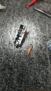
a multi part series (of photos) highlighting how a simple power switch can be quite time consuming. part number esb82101v and 8d15 might be a form factor reference. have to look up 41-10749miw to see whats out there on the internet, other than:


yam 500 - 9.jpg
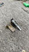
slowly disassembling the switch mech. mini roller wheel makes contact with the copper teeter-totter although that is only the top half of the conduction bar.

yam 500 - 10.jpg
close up of the switch roller.

yam 500 - 11.jpg
the gunk at the bottom of the switch housing probably isnt helping, lets see how bad the contact patch is on the bar.

yam 500 - 12.jpg
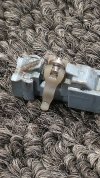
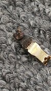
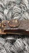
side profile of "the bar" and its 2 piece construction. also 2 different metals which have slightly different conduction properties, not that it matters.

yam 500 - 13.jpg
yup, more gunk to be cleaned. no spray will handle this type of cleaning.

yam 500 - 14.jpg
a mixture of carbon and plastic contamination, plus the spray i tried earlier which only made a larger mess.

yam 500 - 15.jpg
never let spray do a razor blades job, waste of spray. conduction bar and contact rivet cleaned up nicely.

yam 500 - 16.jpg
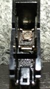
inside the switch house, there is an electrical contact down there somewhere.
 
a closer look at the switch housing clean up plus reassemble.

yam 500 - 17.jpg
utilizing a slightly used piece of paper towel within arms reach, most of the gunk was absorbed/removed from the contact.

yam 500 - 19.jpg
the right tools for the right job.

yam 500 - 20.jpg
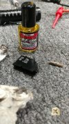
more than just surgery, preventive maintenance via strategic use of a contact conditioner. less resistance between to metal surfaces yields lower loss/energy/heat across the junction. going for the gold.

yam 500 - 21.jpg
reassembled once more although there is an extended story after the first test "attempt" which had no improvement vs original condition.

yam 500 - 22.jpg
this result is after taking the switch apart a second time to re-engineer the mechanical design of the teeter-totter conduction bar.

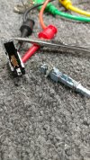
long story short, the hemostats shown earlier were used to bend the lower bar (non-copper piece) slightly upward for a better angle of contact and improved mech action, apparently. the bend point is 1 hemostat nose width below the conduction rivet, where there is an original bend already obvious. a photo would have been easier but too late now.
 

Attachments

  • yam 500 - 18.jpg
    yam 500 - 18.jpg
    101.9 KB · Views: 4
a few more things about the yamaha before the next item.

yam 500 - 23.jpg
power switch, after successful repair and testing, waiting to be soldered for final installation.

yam 500 - 24.jpg
approximate idle wattage, using 40+40w bulbs, most likely closer to 22w but nothing of major concern.

yam 500 - 25.jpg
a quick thermal to verify no other issues or thermal asymmetry between the channels.

yam 500 - 27.jpg
dark spot on the top cover inside, most likely indicating this system has more than a few hours on it. the spot is directly above some higher wattage resistors, most of which run at 140-150f and surrounded by electrolytics (what could possibly go wrong).

yam 500 - 28.jpg
all back together and ready for the out-box rack with the other audio gear waiting for pickup (eventually).

another rotel coming up next, less of a back breaker i.e. under 100 pounds, better yet under 30 pounds (weight not currency).
 
a quick side step about the dim bulb system (v4.0) and its ongoing metamorphosis or mutation as it were.

dim -10.jpg
i found a non polarized down angle plug for the breakout modified inline receptacle. in future it would be easier and better to hard wire this junction. the mount wall outlet is not sturdy enough for single handed plug and unplugging of bulbs but it is good enough for a "mounting" proof of concept.

dim -11.jpg
yes, the exposed electrical connections are a safety hazard so a protective housing or a few layers of electrical tape will be needed. the foot screws in this particular variac end up having a couple threads of bite when adding the thickness of the wall outlet mounting frame. good enough for this design experiment but woefully lacking for mechanical longevity.

a future design mod would utilize x2 foot screw anchors for stability plus the hard wire optimization plus a shallow mount wall receptacle box that is properly grounded. currently using the lower plug position for a narrow yet long term 40w bulb. the upper position has a receptacle expander (x3 three prong outlets) that is used for spacing two bulbs next to each other with an open/unusable three prong outlet in between.
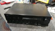
the self-inflicted mess continues.

rotel ra02 - 1.jpg
a sneak peek at the upcoming rotel ra-02, much lighter vs the other rotel's in this thread. might snag a few shots of a sansui au-717 with rack mount face plate handles, still undecided but it needs some love regardless hence being at the repair shop.


225892-bc890408-sansui_au717_and_tu717_includes_rack_handles_and_original_sansui_rack_mount_st...jpg
au-717 example photo (tu-717 makes for a lovely pair) sourced from expired advert:


personally i would put the au-717 on top of the rack minus the chassis cover, but thats just me. unless it was an open top rack, top spot for sure.
 
first batch of rotel photos, customer said right channel no sound.

rotel ra02 - 2.jpg
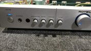
rotel ra-02 integrated amp, 40w stereo 8r and rated for 4r for "a" or "b" channel.

rotel ra02 - 3.jpg
reasonable size heat sink for low wattage output rating. is it me or do the "speaker a" terminals look warped?

rotel ra02 - 4.jpg
either its a qc alignment fail at the factory or someone was mechanically stressing the terminals.

rotel ra02 - 5.jpg
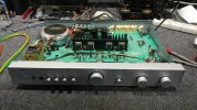
clean pcb design and breathing space for the heat sinks. toroid txf mount plate might cause some issues for a few components.

rotel ra02 - 6.jpg
speaker terminals are definitely flexed/warped. a rather odd occurrence regardless of root cause.


Screenshot 2024-08-08 at 12-44-34 Rotel RA 02 Service Manual PDF Electrical Equipment Electron...png
 
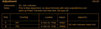
a couple of electrical engineering hints for the upcoming gremlin reveal with the rotel.


A thank you to you -- for your inspiration. Your Yamaha switch repair reminded me of a similar small Yamaha Receiver I have... an R-300.
It has a similar sort of switch, actually 3. Its not worth much, but it lives in a really nice looking faux rosewood; and the tuning pointer does some cool stuff when tuning in stations.
Think the tape mon SW, that kept it dropping one channel, like you say, No spray ever worked. haven't looked at it for many a moon.
Out, and apart it shall come.

I think this thing uses STK modules, :( -- maybe.
Another project...
It's hiding somewhere, so the Yammie might get to see some power pretty soon. More sentimental than anything but the lil guy sounded pretty good.
Pic taken from the Internet...


ea224139-2582-43e8-9b63-0c3f3614c658.jpg
 
conclusion for the little rotel system.

rotel ra02 - 7.jpg
one of the amp output fuses was open, did its job to protect the transistors. no idea if it was due to an unexpected cable short or overloading the amp (low impedance speakers plus high output volume). either way the circuit design demonstrated its benefit.

rotel ra02 - 8.jpg
thermals look balanced when exercising the system, no other electrical concerns present.

rotel ra02 - 9.jpg
low wattage amp idles nice and low even with the 40+40w bulb active.

rotel ra02 - 10.jpg
other than a crunchy sounding tone control switch, which causes one of the channels to cut out briefly/intermittently, the system is ready to be reassembled.

Screenshot 2024-08-08 at 12-55-45 Rotel-RA-02-Service-Manual.pdf.png
brief look at the output fuse part of the schematic. document quality is decent especially for zooming in.

Screenshot 2024-08-08 at 12-59-09 Rotel-RA-02-Service-Manual.pdf.png
dc bias notes for quick reference.
 
Your Yamaha switch repair reminded me of a similar small Yamaha Receiver I have... an R-300.
looks like a cutie with a nicely illuminated tuner and needle. some tuner boxes have no backlight which reduces the visual appeal.


^ If I remember correctly - the pointer which is 2 wide green, with a thin red in between; the intensity of those would change as you dialed in the station -- left vs right green indicator.

My best --
 
forte (threshold / nelson pass) model 4a class-a amp.

forte 4a - 1.jpg
small footprint amplifier, compared to the average chassis sized gear.

forte 4a - 2.jpg
brand logo speaks for itself.

forte 4a - 3.jpg
XLR input signifies "a" model variant hence 4a and not 4.


not much info floating around about the forte amp, like documents or even dc bias value and suggested measurement locations.
 
Back
Top Bottom