• The move to the new server is done. There are some software and database maintenance updates in process. This has us passing the hat around to help out. We appreciate any donations. Seriously, even a dollar helps. The payment page may be found here - https://www.audiokarma.org/support.html

across the bench: an electronic menagerie of diagnostic oddities plus photos and design analysis

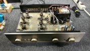
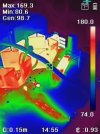
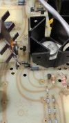
some pioneer photo bombing before a tube amp repair sequence, audion revisited (got toast?).

pioneer 1250 hpm150 - 2.jpg
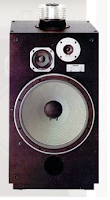
pioneer sx-1250 with hpm-150 speakers

pioneer 1250 hpm150 - 1.jpg
should make for a killer demo depending on a shoppers preference.
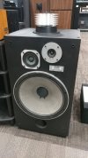
pioneer 1250 hpm150 - 3.jpg
interesting omni tweeter plus a large displacement woofer, should rock the house favorably.


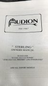
and now a deeper dive into the sterling class-a tube amp.

audion - 01.jpg
not too bad for removing the covers and enough interior wire length to position the board vertical when needed.

audion - 02.jpg
if only they had included a schematic with the manual. tried to contact the company, so far nothing but silence.

audion - 03.jpg
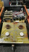
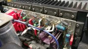
first thing to note, the various burn marks from some obviously hot components. the dual cover chassis design was not a good idea, think heat blanket (on a class-a amp). convective cooling only works IF there is sufficient airflow to complete the circuit. the small array of holes around each tube socket were scarcely sufficient.
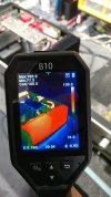
output txf's measure good, wont know if they are fully intact until the 1st part of the repair is ready for testing. need to order some parts for this project plus a few things for the pv5 update/modz.
 
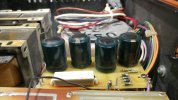
bulging caps and more burn marks.

audion - 04.jpg
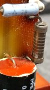
the 100r 7w resistor not only gets hot enough to tan the board but also vaporize most of the silkscreen on the component.

audion - 05.jpg
even the film caps seem to be foaming at the mouth. this must have been a thermal torture test to get such results.

audion - 06.jpg
melted spots on the connection wires, no doubt from the factory. also note the unusual metal stump from a capacitor directly southwest of the black connection wire. better view in another photo, axial cap gone wild.
 
overheated resistor on the sterling plus samwha close up.

audion - 07.jpg
this resistor was being run at a temp consistently beyond its comfort zone. small piece of original shell remaining. also can see how the film cap was reacting to the high heat environment.

audion - 08.jpg
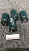
samwha 85c 220uf 250v electrolytic caps, two with bulging tops. closer look at the power resistor with vaporized lettering.


the cap quality discussions are somewhat inconclusive but i have noticed that samwha are of concern, they are also used in older rega audio gear. repaired a rega integrated some time ago and it had thermal management issues plus build quality concerns and samwha caps that had seen better days. with so many variables its difficult to root out a bad/mediocre electronic component brand or series.

an example, a good cap brand/series used in a bad part of a circuit. like a high esr cap in a low esr requirement location. add to that with the thermal limitations of electrolytics and we now have a predictable recipe for low longevity.

audion - 09.jpg
the naked power resistor survived without completely crumbling but without a schematic no certainty as to what its value should be. currently it measures around 4.7k so that is what the replacement will be.

more than a few solder junctions are dry as though the component temp was sufficient to reflow them (not a good thing).
 
last batch of the post-mortem photos for the audion sterling. waiting on the first batch of parts to arrive and then maybe some bottle shopping.

audion - 10.jpg
this shell casing of a capacitor looks like a discharge happened at point blank range, with reference to the pcb. reminds me of a .44 magnum with a really weird primer. this ex-capacitor is probably 10mm in diameter vs 13mm for the magnum, i really should have measured things before attempting an creative comparison. nothing worse than an inaccurate metaphor/simile/analogy +/- 3.1415mm.

*they couldnt even spell simile correctly in the url, how sad.


audion - 11.jpg
looks rather clean inside, this would explain the odd/shredded substance encountered in another part of the lower chassis (shredded rats nest minus the rodents). the half axial body was floating around the chassis, like a spent shell casing in a lunchbox cooler after a day at the range.

audion - 12.jpg
the explosion also explains why the electrode with rubber stopper is hanging out. oddly enough there was a small amount of factory soldered component leg still in the board from the missing half. the detonation sheared the metal leg/lead from the pcb, aggressive kaboom.

a sneak peak for the next batch of thread posts: audio research tube pre and solid state amp.

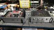
aud res sp9 d240 - 01.jpg
model numbers will be in the next post.
 
audio research specifics.

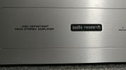
aud res sp9 d240 - 02.jpg
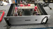
d240 mkii amplifier in decent condition, testing the basics before it sits in the demo chamber.

aud res sp9 d240 - 04.jpg
the large bold font lettering for the model number and exact version (mkii) is nice vs the preamp. the inverting rca inputs require shorting jumpers since there is a scheme to how this can be bridged into mono mode. the cardas shorting plugs were removed prior to the photo.

cardas rcs short.jpeg
i will refrain from the obvious financial retort.

aud res sp9 d240 - 03.jpg
the sp9 mkii tube preamp with the usual cosmetics and functions.

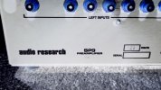
aud res sp9 d240 - 05.jpg
too bad this preamp has zero XLR in/out capability, that would have complemented the amp. notice on the model number it is very difficult to see the mkii designation.

aud res sp9 d240 - 06.jpg
i inverted the photo color (negative) to help show the complete model number. this color option in the software also helps when viewing radiographs like x-ray, mri and ct scans from the healthcare industry since most places are using digital machines vs old school film.


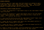
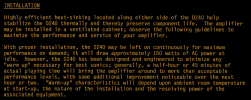
Screenshot 2024-09-19 at 15-37-29 D240II_Manual - D240II_Manual.pdf.png
odd way of doing things but whatever works i guess.

Screenshot 2024-09-19 at 15-42-13 D240II_Manual - D240II_Manual.pdf.png
key takeaway, this thing idles at 150w. i wonder how much of that is in the form of heat. good thing they didnt use many electrolytics but there are a few that will need replacing, hopefully before they fail.
 
a brief look at the preamp and a thermal snapshot.

aud res sp9 d240 - 12.jpg
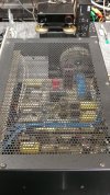
their choice of top cover design should be the norm in regards to enclosed tube preamp or tube amp. conrad johnson would benefit greatly if this design was implement on the pv5 preamp. let all the pretty bottles glow instead of covering up most of them.

aud res sp9 d240 - 13.jpg
the highly ventilated top also makes inspection easier, no need for a screwdriver unless something looks out of place inside.

aud res sp9 d240 - 14.jpg
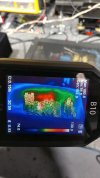
looks like a few hot spots and one of them next to an axial electrolytic. this will need a recap soon, hours of use vs age of caps.
 
a few points to ponder with the d240 mkii amp.

aud res sp9 d240 - 07.jpg
if any component on either of the amp boards needs replacing it will require taking apart most of the chassis plus...

aud res sp9 d240 - 09.jpg
unscrewing a great many expensive sanken outputs (2sc2921 shown). these heat sinks are overloaded due to the densely packed amount of transistors.

aud res sp9 d240 - 10.jpg
there are more down the sides and across the bottom of the heat sink. if something goes boom, it aint gonna be pretty to clean up the aftermath.

aud res sp9 d240 - 11.jpg
at least there is a large number of film caps which tend to tolerate high heat environments better than electrolytics. the presence of carbon comp resistors is not reassuring in regards to longevity.

thermal scans for the d240 show an imbalance on the left channel rear heat sink, will be shown in the next post. also this amp hates dim bulb or it might be pointing to an age related issue slowly cropping up. 280 watts of bulbs seems to stimulate issues with the left channel (nothing connected). dc offset L-ch was showing 2-5v dc, not milli-volts. havent noticed any adjustment pots for offset or bias, need to study the schematic before any conclusions.

taking the amp off the dim bulb chain things started to function normally although R-ch had no issues with offset when using dim bulb. left channel still showed elevated offset but slowly found its way to zero (warm up reaction).
 
d240 thermals and the imbalance, servo amp self controlled.

aud res sp9 d240 - 08.jpg
judging by the schematic the axial electrolytics go between rail voltage and ground. so if one or both dry out and start showing more of a resistor trait things will be messy. at least the outputs should be unaffected, theoretically, so shorting a rail to ground would be the lesser of the evils.

aud res sp9 d240 - 15.jpg
left channel, interesting to note minimal immediate heat near the rear left corner of the chassis, where the large electrolytics are housed. looking good so far for cap health potential.

aud res sp9 d240 - 16.jpg
right channel, rear heat sink looks like it is running slightly cooler vs the front sink. noticeable difference vs left channel.

aud res sp9 d240 - 17.jpg
rear board hot spots. chassis should be fine until it heat soaks to the overall idle temp/wattage at which point all bets are off.

aud res sp9 d240 - 18.jpg
slightly better angle of the left thermal concern and its proximity to the rear board electrolytics.

aud res sp9 d240 - 19.jpg
right channel, yeah there is definitely a transistor biasing variance most likely due to an out of tolerance servo control circuit. unless the system is designed to warm up one channel at a time the temp measurements might point to a circuit anomaly.
 
and now the audio research dynamic duo is out in the demo arena waiting to catch somebodies attention, in a good way.

aud res sp9 d240 - 20.jpg
group photo of audio research, carver, mcintosh, marantz, parasound (modified sleeper amp) and a bluesound streamer hiding in the shadows.

aud res sp9 d240 - 21.jpg
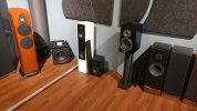
a mixture of audio transducers as well, floating around the battlefield. wharfedale jade-5, JL audio sub, martin logan in white, elac carina, heco and a couple pairs of older advent towers in attendance. klipsch, apogee and polk on the other side, sorry no photo.

some updates about the cj pv5 overkill upgrade in the next post. still working on the citation 16 and audion tube amp plus a few pairs of speakers.

oh the horror of interacting with various audio gear at multiple levels and the burden of testing fine products regardless of age.

why are there so few who would find this type of activity stimulating?

*a different form of stimulation.
 
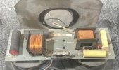
polk rta 12b fuse closer inspection.

polk 12b - 7.jpg
from the previous page of activity.

polk 12b - 8.jpg
thats a rather high rating.

crossover mounted fuse looks a bit too hardy
it would appear that a 15a fuse found its way into the system. might explain why the tweeter is silent when testing.
 
polk rta 12b fuse closer inspection.

View attachment 3303365
from the previous page of activity.

View attachment 3303366
thats a rather high rating.


it would appear that a 15a fuse found its way into the system. might explain why the tweeter is silent when testing.
Yep, it`s end cap stamped value that you found ^^ doesn`t surprise me at all from glancing at your earlier first picture of the removed crossover!
Silly stupid desperate clueless human like fools can be very destructive, and I would have bet my life that the tweeter that that fuse position was meant to protect was burned open, as I`ve encountered this type of brainless over driving amp clipping abuse scores of times since 1970 when I started helping clueless friends to trouble shoot their various audio system`s faults/failures.
 
more info about the on going conrad johnson pv5 project.

cj pv5 - 19.jpg
tube preamp runs fine even when the carbon comp resistor goes a bit high, just a few hundred percent beyond tolerance no big deal. once upon a time this was a 390k component (maybe 30 seconds after manufacturing).

cj pv5 - 20.jpg
a closer look at how the output relay is supposed to function which led to its contacts needing some attention. the system is design so that when the relay is not energized the outputs are shorted, no noise going to the power amp (makes sense... now). so when a person hears the click about a minute after pushing the power button (rc time constant) it is opening the grounding circuit so that a signal can now flow to the output device (power amp). which takes the relay completely out of the signal chain, some purists will love this design solution since relay contacts are not known for their clean conduction surfaces nor perfect signal transfer without affecting signal quality.

cj pv5 - 21.jpg
the circuit board received a hair cut and now there is far better thermal breathing room and improved capacitor lifespan. the electrolytics will still be of some concern but improved air flow may win the day. plus 105c rating for the tall power caps and 125c or 135c for the shorter low voltage power cap (feeds relay and tube heaters) will certainly add years of lifespan.

ideally just need to replicate the audio research preamp chassis cover plus adding the same style of ventilation to the sides of the cover and this 8 bottle unit will perform far longer than the ill fated stock parts cooker design. txf and low voltage rectifier would be next on the ultimate modz list but not for this project, owner has a budget limit. thank goodness this pv5 had low hours and was a treat to repair and upgrade.

cj pv5 - 22.jpg
one design benefit cj has with this preamp is having a deep belly pan with tall pcb mounting points. guess where all the new (mostly 630v rated) film caps are hiding. also added some films to the rectifier side of the high voltage electrolytic. initial power up measurements, the original 400v films were being subjected to over 500v for a few seconds after power up and then the voltage stabilized around 430v constant. that would explain some of the film cap failures found in the previous "cooked" pv5 repair several months prior to this project (design issue).

some updated thermals in next post, going from 1.2k 2w to 1.5k 10w helped reduce resistor temp by 100f in the power supply area (next to the electrolytics).
 
capacitor leakage, electrolytic vs film info:

youtube.com/watch?v=cqqBwyfPbKc
*xraytonyb video

youtube.com/watch?v=lLQThhf3Brc
*mr carlsons lab, cap tester comparison
 
pv5 thermals so far, before the next batch of adjustments.

cj pv5 - 23.jpeg
first attempt at improving the 390k resistor, formerly the out of tolerance carbon comp.

cj pv5 - 24.jpeg
it would have been nice if the relay circuit reduced its latch voltage slightly to minimize waste heat, like the apt holman preamp design.

cj pv5 - 25.jpeg
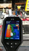
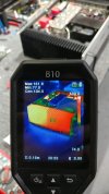
the 10w resistor is about 100f cooler than the 2w that was factory installed. larger surface area helps reduce heat density. the oddball tall heat sink at the bottom of this view has a transistor body temp of 200f, hopefully the inbound replacement transistor helps reduce that.
 
a few more thoughts prior to the final pv5 upgrades (more parts arrived).

cj pv5 - 26.jpg
the small mps a42 (q2) sandwiched between the raging inferno q3 (mje 340) and the moderate temp of 7812 (mc7812ck) regulator sink. since q2 operates at a cooler temp it will be relocated under the board to keep the film caps company. q3 will obviously stay top side due to its considerable thermionic activity. q1 (mps a92) which is north of the series herd of zener diodes also hits a high temp similar to r2 (390k). the next replacement for r2 will involve a pair of 820k 3w in parallel which should drop the operating temp favorably.

looking at the pv5 parts list again, it would appear that the original carbon comp 390k was rated for 1w, that explains a few things and the predictable failure mode even on a low hours preamp. r2 gets hit with around 500v dc and if we do some cheap and easy math (v^2/r) the amount of torture the carbon comp is subjected to (at every power up) is around 640mw which is within the 1w design limitation. the voltage settles down to around 440v which would be 496mw, still not an issue unless the resistor is carbon comp. as r2 ages and the constant thermal stress accumulates the resistance drifts higher (as expected) which then reduces heating effect and most likely starts to skew the q1/2/3 regulator for high voltage to the tubes.

so, if r2 goes up how does that affect the power supply? guess i will be measuring that too since the new 390k is getting updated (again). the 10 pack of series 1n5257b zeners points to a reference voltage of 330v for the q1/2/3 regulator/filter which is a substantial drop from the 500v power up and 430v idle that is measured after the rectifier.

more design notes for a future "what if" that may never happen. cant say i am expecting to see another pv5 in good condition, or at all, any time soon after this little beauty is completed.

i really need to stop digging a deeper hole than what is necessary.
 
progress on the citation 16 plus the joys of broken solder joints, one from when the amp left the factory.

hk cit 16 - 32.jpg
repairs are progressing slowly, bumping into more age related quirks here and there. solder quality of the boards and connecting wires from the amp output transistors to the relay board. oxidation is just the tip of the iceberg with this amp. plastic face plates need some structural improvements, they did not age very well (havent fallen off yet).

hk cit 16 - 33.jpg
relay instabilities that can be triggered with a simple tap on the plastic test.

should have this one wrapped up soon after a few more new parts arrive. the 1 meg ohm single turn pot in each channel (for dc offset) was not a good design idea, very sensitive and prone to drifting far too much.
 
Back
Top Bottom