

You are using an out of date browser. It may not display this or other websites correctly.
You should upgrade or use an alternative browser.
You should upgrade or use an alternative browser.
across the bench: an electronic menagerie of diagnostic oddities plus photos and design analysis
- Thread starter sae-7125
- Start date

sae-7125
Super Member
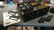
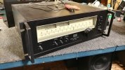
sansui au-717 needs a recap and the usual transistor updates. switches and pots were not noisy on this one but they are getting sprayed regardless.
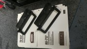
manuals and schematics also accompany each device. rack handles are for the 717 since the 517 has a pair installed already.
sae-7125
Super Member
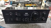
face plate in decent condition, no sign of wild parties or being dropped down a flight of stairs. the 717 looks so much nicer with the top down, leave the lackluster chassis cover in the storage closet where it belongs.
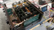
a small piece of screen mesh, similar to what is used on some mcintosh gear (mesh cage), could be fabricated to cover the amp boards and power board. perhaps a t-top with three small neodymium magnets to hold the screen in place. or a two piece bikini one for each pcb area, either way the heat sinks would benefit from greater air flow.
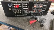
phono shorting jumpers factory installed and the spring loaded speaker terminals are still healthy. although this might receive a banana terminal upgrade like a previous system i posted in the sansui section of audiokarma.

zenith2134
Lunatic Member
Those tweeters aren't half-bad.
sae-7125
Super Member
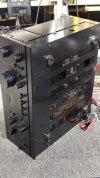
the usual amount of ventilation for these integrated amps and they need it too. lots of hot spots and near various electrolytics especially on the au-719. the 717 doesnt have an issue with 40+40w dim bulb even when slightly exercising the outputs. the last 719 i worked on was not happy being restricted by the bulb, too much of a choke chain or doesnt like being domesticated/house-trained.


sae-7125
Super Member
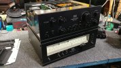
that should do it for the initial inspection for this dynamic duo, tu-517 + au-717.
Sansui TU-517 | hifi-wiki.com
Sansui AU-717 | hifi-wiki.com

Chris & Justin's Sansui AU-717 Restoration
Sansui AU-717 Integrated Amplifier Here we have two very clean Sansui AU-717 Integrated Amplifiers that came in for a restoration...
 marantzhallo-fi.blogspot.com
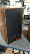
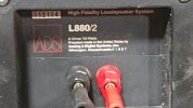
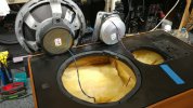
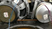
sae-7125
Super Member
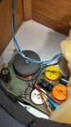
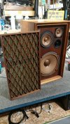
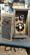
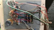
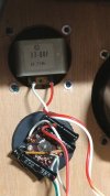
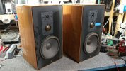
pushing the fiberglass insulation aside to look at the xover
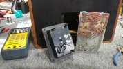
removed pcb from the terminal cup, overall relatively simple to access. starting with a recap even though the midrange took a hit.
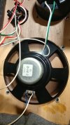
LCR meter is showing a different resistance and inductance vs the functional speaker. the midrange in this cabinet has lower resistance at 1khz and 2-3 times the inductance of the known good driver in the other cabinet.
there is mention of ferro-fluid for the tweeter which might be another area of concern/inspection. even though the tweeter in each cabinet is functional.
Which ADS tweeters use ferrofluid?
Hi! Is there a list of all ADS tweeters that used ferrofluid? ADS speakers are well liked but this ferrofluid business... I'm having second thoughts. I'm sure they sounded great when new but I just found out about ferrofluid and it scares me. Apparently the ferrofluid loses quality over time and...
audiokarma.org
sae-7125
Super Member
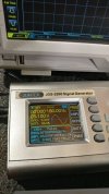
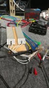
freq gen set to the usual 100hz 1.8v rms for the signal source
*output bottle spec sheet
sae-7125
Super Member

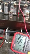
measuring across one of the outputs (anode/plate to cathode) at idle with ~26mv bias

turning up the volume until just before clipping. doing some calculations 470v dc across the bulb and measuring 125mv of bias equals 58.75w at 100hz. wave amplitude in the background is 22.6v rms which equals 63.8w per channel (both bottles together, push pull).
now i am starting to see why solid state equivalent output wattage needs to be x2 or 2.5 vs tube power output. the EL34 system is usually rated for 30-38w/ch so this is an interesting experience to help solidify why the conversion calc is what it is.
max wave form testing was in 5s intervals so the new outputs (~4h burn in previous) dont get over cooked. should have done some thermal scans inside the chassis to evaluate hotter than normal-operation spots.
sae-7125
Super Member
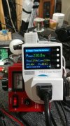
normal idle ~130w at 26mv bias (all four outputs stable) vs 230w for single channel max testing
a high voltage low current design definitely has its benefits especially being far more tolerant of high ripple from the power supply 1v tube vs 1mv solid state. the new technology that has sustained solid state for decades could certainly enhance tube performance and stability, primaLuna is one premium example.
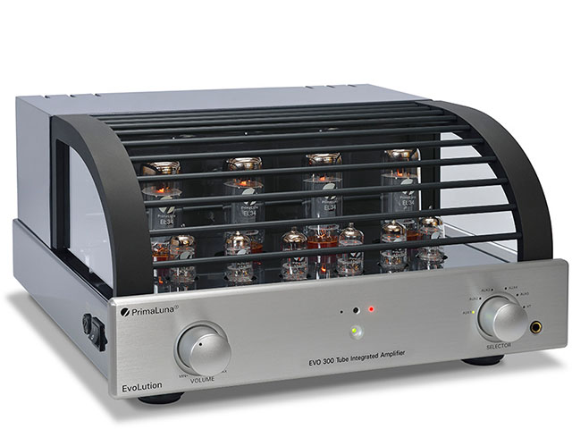
PrimaLuna I Tube Amplifiers
Since 2003 our PrimaLuna Tube Amplifiers, Tube CD Players and Tube DAC receive raving reviews and Best Product Awards from renowned HiFi magazines from all over the world! Enter our website to learn more!
 www.primaluna.nl
sae-7125
Super Member
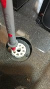
something interesting to note about the jolida and the intermittent over-biasing/red-plating of a specific output location. some of the pin sockets seem to have stretched over the years. dmm probe is smaller in diameter vs tube pin but it is a suitable feeler gauge (think spark plug gap for internal combustion vehicles) showing how much space between the contacts.
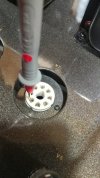
carefully bending the socket electrodes inward helped eliminate the occasional issue. bending each side of the socket to the point that it makes contact when testing with the dmm probe should be sufficient.
an intermittent electrical connection with a grid pin, what could possibly go wrong... typically happens when doing a cold start with the system. buzzing/arcing muffled by the ceramic socket although the heater/filament area (center of the tube) slowly gets brighter plus eventual crackle sound on the channel speaker.
too many lumens of brightness from the heater core area is a good indicator of something going wrong.