• The move to the new server is done. There are some software and database maintenance updates in process. This has us passing the hat around to help out. We appreciate any donations. Seriously, even a dollar helps. The payment page may be found here - https://www.audiokarma.org/support.html

across the bench: an electronic menagerie of diagnostic oddities plus photos and design analysis

cj pv5 - 6.jpg
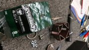
zeners updated, perhaps overkill now judging by the updated thermals. unfortunately the originals are time bombs after a few cooking cycles over the years.

added heat sink to the inferno mje340 npn, definitely helps but a better solution still needs to be found. relay removed for output disruption testing, yeah lots of dc output with power off action. modded red class-d power amp channel protection definitely works though and bench speakers survived.

obviously the relay returned and some rc timing adjustment transpired, electrolytic replaced with film of lower capacitance.
 
cj pv5 - 7.jpg
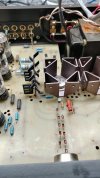
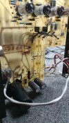
doing something different with the 12v reg's feeding the filament/heater circuits. fyi, pcb is not a good heat sink... hello lift kit, gonna take a couple nuts each to do it.
 
Screenshot 2025-12-12 at 14-33-30 E180CC _ 7062 _ 5965 _ 6829 - AB2B2C - Vintage electronic tu...png
comparing glassware is a headache all of its own

the more i work on cj pv-5's the modz start to become more invasive. and then there is tube shopping for better bottles which has its own complexities. havent noticed much to improve on the 5751 but something might exist.
 
obviously looking into b+ rectifier diodes (fred, hexfred, fast vs ultra fast, soft recovery...) will happen eventually.

perhaps a reduction of the 12v reg's to evaluate the heater resistor design used on/in harman kardon citation ii amps with the 12by7a front end. maybe even ditch the heat sink reg's for a different scheme, 11v zeners or something. too many what if r&d around the bench.


*txf snubber could be useful, maybe tune prime and 2nd.
 
cj pv5 - 13.jpg
full mains testing, seems to hold electrons with no major leaks. output relay missing at this point in time, it was reinstalled later in this rejuvenation/rework/repair/redesign project.
 
cj pv5 - 14.jpg
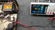
baseline mains numbers, unknown hours and stability with the bottles. some of the 5751'a are very microphonic so that will need eventual replacement.
 
cj pv5 - 15.jpg
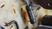
even a low hours system can have a pcb burn mark, from the 1.2k crc filter resistor. replaced it with a 1.5k higher wattage component which helped to lower thermal intensity.

ended up adding a 4.7k 1w in parallel under the pcb for 1.15k equivalent which reduced the hot spot even further (260f to 180f). seems like the original 1.2k cooks around 300f, need to check past notes.
 
cj pv5 - 16.jpg
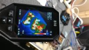
looking at overall system health and thermal response. also sonic testing, output relay not reinstalled yet hence the lack of a thermal signature in that area of the board.

relay solenoid gets hot (120 dcr coil, 12v feed), another area of concern to be modified.
 
in regards to relay circuit design and dialing back the voltage after the relay hits latch/lockup position, maybe borrow a chapter from apt holman preamp. been there, done that... freaking weak rectifier causing issues on the system i repaired several pages ago. so simple and yet such a headache to realize.


cj pv5 - 17.jpg
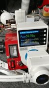
interesting to notice the mains fuse temp, indicator of system idle load. obviously an inline ammeter with data logger ability would be ideal.
 
cj pv5 - 18.jpg
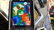
looking at the mje340 additional/modz heat sink temp which is mounted to the rear of the transistor (exposed metal side).

both heat sinks have higher grade thermal paste applied, should help as well. a temp of 160f is an improvement vs original 270f or higher.

*starting to wonder if 0.3 meter (11.81 inches) distance setting is an ideal distance with my measurements or if 0.15 meter (5.90 inches) would be better. further testing needed, not that what i do requires 10 decimal places of accuracy.
 
cj pv5 - 19.jpg
looking at rectifier temp mounted to bottom of the chassis. seems to maintain around 115f vs original on pcb around 250f.
 
Back
Top Bottom