• The move to the new server is done. There are some software and database maintenance updates in process. This has us passing the hat around to help out. We appreciate any donations. Seriously, even a dollar helps. The payment page may be found here - https://www.audiokarma.org/support.html

across the bench: an electronic menagerie of diagnostic oddities plus photos and design analysis

bryston 4b - 5.jpg
roe power caps from west germany, 10000uf 80v and clamps allow for 50-51mm diameter which sets the stage for cap shopping parameters.
 
bryston 4b - 7.jpg
idle wattage also healthy and on the high side and yet...

power caps rated for 80v and the rails are at 80v with 115-117v on the mains. wonder what happens when 120v and higher is applied i.e. the typical modern household. these vintage bryston 4b systems definitely need a recap, over-voltage can only be tolerated for only so long before entering kaboom territory.
 
bryston 4b - 8.jpg
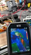
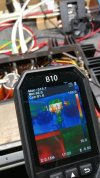
identifying hot spots at idle and how damaging the factory design flaws will be. pair of 5.6k resistor for the front panel LED circuit are cooking at over 300f. pcb turning into charcoal.
 
bryston 4b - 9.jpg
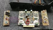
hot spot on the narrow boards that have output/driver transistors mounted on them. sockets soldered to board and no the outputs are not class-a inferno idle design.
 
Screenshot 2025-12-24 at 17-52-04 Bryston-4B-pwr-sch.pdf.png
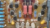
the two pairs of hot resistors look to be part of the dc offset circuit (180r voltage drop is key to circuit/system offset, according to a simple circuit sim).
 
Screenshot 2025-12-20 at 16-34-41 Bryston-4B-pwr-sch.pdf-box.png
one cooker resistor per channel and a transistor connected/close to the inferno

Screenshot 2025-12-20 at 16-36-05 Bryston-4B-pwr-sch.pdf.png
comparing to a different version/revision level. using 24v zener plus lower resistance, no idea if the resistor still gets cooked.
 
bryston 4b - 10.jpg
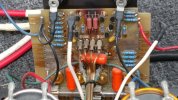
the two pairs of hot spot resistors have no problem cooking the electrolytics next door since the left channel positions the caps over the resistors.
 
bryston 4b - 11.jpg
for reference 85c = 185f and 105c = 221f, in regards to electrolytic temp ratings.

at idle the large side wall heat sinks are not an issue. when exercising the system that thermal situation changes quickly.
 
bryston 4b - 12.jpg
pair of 470uf caps are in parallel as shown in the schematic snippet posted earlier. the update/modz solution will involve a 1000uf in parallel with 8uf film as a thermal shield/barrier wall. not to mention the pairs of 1w resistors will get a wattage rating increase.

havent decided what to do with the 180r offset situation. possibly replace with 0.1% 1k and then modify resistance with a parallel value (220r +/- ~r) to dial in a near zero offset or something. need to complete the primary rebuild first and then adjust the system from the new stable baseline, if needed.

larger value resistors have higher thermal noise component so maybe a multi-turn 200r pot + 100r 0.1% would be better. balancing the two narrow boards per channel might increase complications i.e. too many variables.
 
bryston 4b - 13.jpg
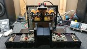
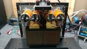
bryston on its face without the amp channels. mains txf's are rather heavy boat anchors in the equation, could have some fun with a different ac/dc front end but this isnt my amp to experiment with.
 
bryston 4b - 16.jpg
there are a few potentially sensitive components in the thermal blast radius, transistors and tantalum caps. diodes might be affected as well especially zeners.
 
bryston 4b - 19.jpg
removing components and inspecting broken solder joints on the output transistor socket pins. need to reflow most of the connections even though its a double sided board.
 
Back
Top Bottom