• The move to the new server is done. There are some software and database maintenance updates in process. This has us passing the hat around to help out. We appreciate any donations. Seriously, even a dollar helps. The payment page may be found here - https://www.audiokarma.org/support.html

across the bench: an electronic menagerie of diagnostic oddities plus photos and design analysis

cj pv5 - 20.jpg
improved ventilation possibility although spacers and longer hardware would be needed for the top

cj pv5 - 21.jpg
side screws make this position easy, possibly use large diameter washers to help hold the chassis top in place. mounting hardware on top would still be a better idea in regards to child safety testing.

caps are not a permanent addition, just improving air flow for bench testing. taller chassis legs/feet wouldnt be a bad idea. perhaps vibration absorbing options since microphonic tubes can hear anything (sonic, electrical and mechanical noise).
 
cj pv5 - 27.jpg
closer look at the reinstalled relay and its circuit modz. the factory 47uf electrolytic has been replaced with a pair of 1uf film caps which greatly shortens the rc time constant. ideal click time after system power up might be somewhere around 10 seconds or down to 6 seconds.

in terns of heater/filament health or cathode health and longevity using higher grade glassware might offset any lifespan reduction, assuming there is any measurable injury to the bottles when signal is applied a few seconds after heater is active.

most likely a concern for direct heated triodes only.
 
Screenshot 2025-12-20 at 13-35-19 pv5.gif (GIF Image 1448 × 1076 pixels).png
circuit design, might wire this up in a sim to evaluate modz better

the 1 minute or beyond that the factory set was most likely for minimizing power/wake up noise that tube systems naturally produce.

the 3.5s click time right now is a little too short but it will be dialed in eventually. adjusting the 1.2meg resistor upward plus adding a higher value film cap should take care of things nicely vs waiting for what feels like an eternity before the relay clicks after power up. it could be that q4 or q5 are out of spec but its a trivial concern at this point.

another note is circuit discharge rate, you want the relay to de-energize fast as possible when cycling the power button. the relay on this system shorts the output when power is off and for good reason. large dc spike to the power amp when turning off preamp before power amp.
 
cj pv5 - 28.jpg
the jj double cap on its side to fit in the chassis with wire extensions. also small chassis ground cap moved to top side of pcb vs under as shown in previous photos.
 
cj pv5 - 29.jpg
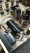
hot melt glue sufficient for the big, and potentially temporary, low temperature cap. lots of breathing room on deck which will help with air flow and fewer film caps getting melted.
 
cj pv5 - 23.jpg
some performance testing before the preamp spends time in the new demo chamber to evaluate overall performance. the next batch of modz will be fine tuning the power supply cap, relay timing, new or nos bottles and maybe some premium output caps.
 
cj pv5 - 24.jpg
exterior thermal scan, technically the outer shell is reversed since the vent is normally over the mains txf and power supply caps. its nice that the mounting screw holes line up perfectly to move ventilation somewhere that is always hotter i.e. over the tubes. should improve convection cooling even though the line stage tubes are still covered. heat is being directed away from the power supply electrolytics and allowed to exit quicker.

might be a while before the "round 2" updates are installed, timeline uncertain.
 
*looks like pro version with XLR inputs

*talks about newer 90's 4b with smaller power caps
 
bryston 4b - 2.jpg
taking a look inside the bryston. system is functional, one channel had most of its outputs replaced at some point in time. the other channel looks original, no signs of a recap or extensive circuit changes/repairs/modz.
 
bryston 4b - 3.jpg
modular channel removal interesting to see. unfortunately desoldering components requires removing all the output transistors which is messy. i wonder how many amps the sliding pin edge connectors are rated for. definitely going to need contact enhancer to reduce junction resistance for improved output.
 
View attachment 3660010
modular channel removal interesting to see. unfortunately desoldering components requires removing all the output transistors which is messy. i wonder how many amps the sliding pin edge connectors are rated for. definitely going to need contact enhancer to reduce junction resistance for improved output.
I use Stabilant22 for that.

What's your preferred contact enhancer?

Nashou


Stabilant22
cant say that i have bumped into stabilant22/22a although there hasnt been much of a deep dive into contact cleaners and enhancers in my day-to-day activities.

typically use this in various areas but i am finding deoxit in general tends to fall short on some types of surface corrosion and switch contacts. better off rebuilding the switch which is quite messy or not possible.

the high temp rating, which has an asterisk warning, seems to help signal tube pins oddly enough.

more research is needed to find a somewhat universal contact cleaner/protector/enhancer. zero brand/hype loyalty will be needed as well for a suitable comparison.


various links for future reference, maybe it will help me focus on the topic in general.
 
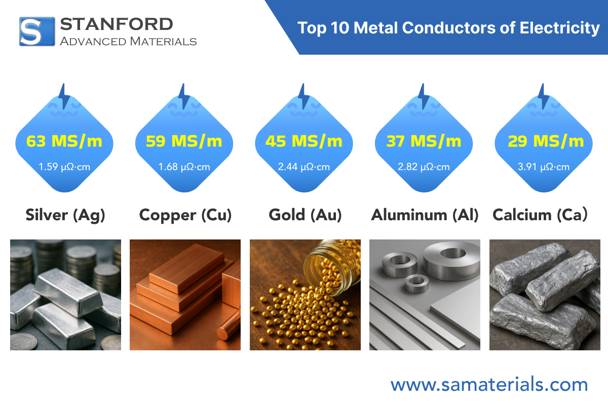
materials comparison

graphene contact enhancer
 
Back
Top Bottom