You are using an out of date browser. It may not display this or other websites correctly.
You should upgrade or use an alternative browser.
You should upgrade or use an alternative browser.
across the bench: an electronic menagerie of diagnostic oddities plus photos and design analysis
- Thread starter sae-7125
- Start date

sae-7125
Super Member
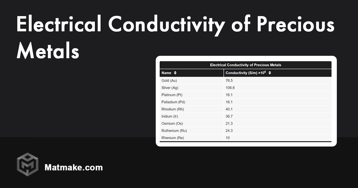
Electrical Conductivity of Precious Metals - Table
Find the electrical conductivity values for different precious metals in Siemens per meter (S/m) units.
 matmake.com
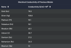
comparing silver/gold/platinum/rhodium when shopping for higher grade speaker terminals. funny how premium prices are paid for inferior conductivity materials (profit bait? vs price per gram).
sae-7125
Super Member
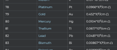
Reference Table of Elemental Electrical Conductivity - Alfa Chemistry
Alfa Chemistry provides the following table to help you understand the electrical conductivity of the elements in the periodic table.
www.alfa-chemistry.com
interesting to also look at titanium/tin/lead for a numbers comparison. perhaps lead+tin solder isnt so terrible vs a crimp termination for wiring connections (power caps, rectifier, amplifier output).
perhaps screw terminal power cap alternatives should be considered even though more work to do the conversion. the difference between 20000uf and 30000uf upgrade caps is significant, pricing was better as well...

sae-7125
Super Member

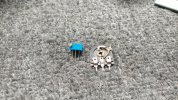
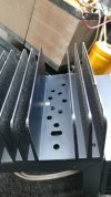
looking at upgrading the wiring which might be more of a hurdle than anticipated. the skinny/anorexic wire in the middle is from mains rectifier to one rail of the power caps, possibly 18ga aluminum by the looks of things.

AWG - Wire Gauge Sizes: Current Ratings, Charts, Measurements, and Conversion Guide
Amp ratings vs. US AWG wire gauge.
 www.engineeringtoolbox.com
so stock wire is most likely adequate when calculating 3-5a at 80v per rail which equals 240-400w per wire. thermal derating is one potential restriction i.e. running a 15a household circuit at 14a is possible but things are going to melt +/- catch fire at some point. the scrap pieces of copper 14awg in the photo, from a powered sub amp output, will be a healthier choice not to mention allowing high power dynamics to breathe easier (think dim bulb restriction vs full mains).
only problem is upgrading the 3 wires going from power caps to each amp board. technically the wires connect to the rear board backplane before feeding through an edge connector (massive restriction?).
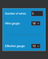
adding two more 18awg wires (+/gnd/-, 1 vs 3 wires each) to the rear board would be an improvement especially if using copper single core. realistically speaking the factory wires are sufficient for the dynamic wattage task but we can do better. since there are more than a few pairs of inefficient difficult to drive speakers out in the world that are fun to exercise.

sae-7125
Super Member
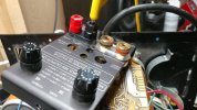
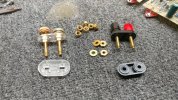
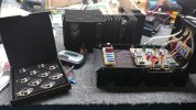
comparing bind post performance and if the deeper alternative is usable
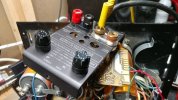
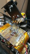
better stability with the alternative posts, mounting both pair had issues so something else will be needed.
drilling out the shallow depth of the original posts helps but it still falls short in some areas.

sae-7125
Super Member
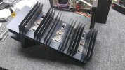
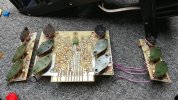
rebuilt channel ready for testing, other channel is unmodified so far. initial thermal scans showed improvement after some brief testing, no more 315f/157c and beyond component temps.
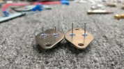
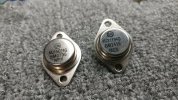
ideally all of the small signal transistors on the rear board should be replaced due to excessive/senseless high temp exposure. starting to wonder about the 2n5400/2n5550/2n5210 on the amp boards since they have a noise figure spec, fluttering dc bias is concerning.

gslikker
Super Member
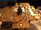
Can you imagine, Years ago I gave up on a 4B, which I knew was used as a PA amp in a rack.
As this amp does not get proper cooling it heated up itself to death and EVERYTHING plastic, even the fuse holders, connectors, etc was compromised by the heat. pcb's were all browned out and it was repaired, before.
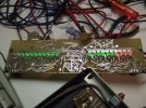
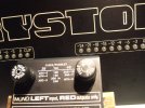
This was the model having a full row of dual color LED's.
The input board on the back did have an extra transformer to supply power for the LED displays.
Probably these were a short lived series, as they even had the silkscreening worng on the board and they used 7 Volts (as per design) to feed TTL chips!
(they are specified for 7V max yes, but as everybody knows TTL is supposed to run on 5V).
It had toroid transformers (humming with no load only the old caps) and one displaced rectifier to make room.
It just was not worth repairing, browned out amp boards are conductive....
However, I did keep the front plate and the LED row display as the circuit simply works (whether on 5 or 7 Volts, maybe I ever make a wooden enclosere with a little psy and have a nice VU meter....
For leisure, I still have pictures of the transformer having the silkscreen wrong way around (or was it inverted tracks ) and the LED VU meter row.
I know, I should have put more effort in it, as by then I only thought it to be "some PA amp" but it seems to be rather scarce when looking for pictures......

As this amp does not get proper cooling it heated up itself to death and EVERYTHING plastic, even the fuse holders, connectors, etc was compromised by the heat. pcb's were all browned out and it was repaired, before.
This was the model having a full row of dual color LED's.
The input board on the back did have an extra transformer to supply power for the LED displays.
Probably these were a short lived series, as they even had the silkscreening worng on the board and they used 7 Volts (as per design) to feed TTL chips!
(they are specified for 7V max yes, but as everybody knows TTL is supposed to run on 5V).
It had toroid transformers (humming with no load only the old caps) and one displaced rectifier to make room.
It just was not worth repairing, browned out amp boards are conductive....
However, I did keep the front plate and the LED row display as the circuit simply works (whether on 5 or 7 Volts, maybe I ever make a wooden enclosere with a little psy and have a nice VU meter....
For leisure, I still have pictures of the transformer having the silkscreen wrong way around (or was it inverted tracks
) and the LED VU meter row.I know, I should have put more effort in it, as by then I only thought it to be "some PA amp" but it seems to be rather scarce when looking for pictures......
sae-7125
Super Member
seems consistent with vintage and modern designs. nice batch of photos.does not get proper cooling it heated up itself to death
sae-7125
Super Member
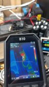
channel with updated resistors, max temp around 175f/79c. film cap functioning as a heat shield quite nicely, as intended. electrolytic on top nice and cool, modz design success.
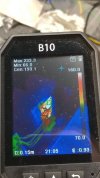
comparing temp to unmodified channel even though hot resistors are above the caps.
going from 232f/111c down to 175f/79c should be an improvement if anything and this is at amp idle with the top off. a heat soaked system with interior ambient temp around 104f/40c will bump up the hot spots (thermal derating concern) by a few degrees.