• The move to the new server is done. There are some software and database maintenance updates in process. This has us passing the hat around to help out. We appreciate any donations. Seriously, even a dollar helps. The payment page may be found here - https://www.audiokarma.org/support.html

Acurus L10 problem

KNielsen

Well-Known Member
Hey AK

I got some problems with a newly modded Acurus L10 preamp.
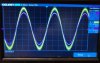
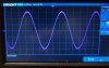
Depending on the volume, the left channel playes louder then the right. Worst at about 12 o'clock volume on the scope.
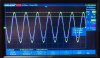
The two channels lines up to around 9 o'clock and then split on the o.scope, and after 12 o'clock the start to meet again till full volume....?? I've cleaned the NOBEL pots, could this be the reason??

(Pic1) 9 o'clock
IMG20230114222006~2.jpg

(Pic2) 12 o'clock
IMG20230114222022~2.jpg

(Pic3) full volume
IMG20230114221904~2.jpg

There is some gnd-noise on the yellow trace from the probe, but it doesn't matter.
Input voltage is 1kHz/100mVpp ..

When music is applied, it's quite noticeable from around 9 o'clock, where the left speaker becomes more present
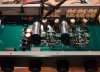
IMG20230114223602~2.jpg
The constant current source is dead on 250-252μA, so this should be good compared to premeasurments before the CCS where build.
The rest follows newer model schematics.

Sadly I didn't measure if there were any channel differences before I started soldering, so I don't know if this where present before

Best regards
 
Last edited:
Register to hide this ad
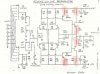
Acurus-L10-schematic~2.jpg
I have been measuring some differences between the two channels from R16/R17/Q5/Q6 and forward marked with red, but neglected this as variation in the transistors.. this section is untouched, and stock resistors also

Do you have any suggestions @mondialfan

Best regards
 
Last edited:
Left Ch. / Right Ch.
R16: 0.593V / 0.570V
R17: 0.594V / 0.569V
R18: 129.8mV / 154.2mV
R19: 129.8mV / 152.6mV
R20: 129.3mV / 153.8mV
R21: 130.0mV / 152.9mV

All transistors passed the diode-test in circuit, and looked at the pots once again and measured resistance. All good.

Managed to get rid of the noise on the scope and took a new picture at 10 o'clock 1kHz/200mVpp input.
The difference is approx 16mV between the two curves at the output. At 12 o'clock there is approx 38mV difference
IMG20230115012038~2.jpg

I measure a 20mV DC-OFFSET across the 10μf cap on the left channel and 40mV across the right Ch.. 0mV on the output as it should
 
Last edited:
I changed Q5/Q6 and ended at 1.3mV difference at 10 o'clock on the volume between the L/R Ch @1kHz, 200mVpp input.... Much better the previous 16mV as posted above.

Afterwards; while I were at it, I matched a new pair for the diff-section and ended at -0.5mV and 1.5mV DC-OFFSET before the 10μf cap, instead of 20mV and 40mV.
I can't come any closer for now...
All soldering has been redone, also the original solderings, just in case

Regards
 
Last edited:
Since I'm talking to myself, I'd might just continue :)

Maby a bit closer (after listening to the preamp this evening), made a new CCS, just to be picky:
Did a quick match of the transistors and diodes used in the new CSS.. Target was 248μA..
Result for the 4 CCS: 248μA/248μA/248μA/250μA
Hence it's fairly easy to calculate a CSS, I do not see this as the endgame. But, then I know I've done all possible.
New measments of the preamp tomorrow.
If this is a deal-breaker then I've made a mistake in previous CSS (and measurements of the CSS!???), although I've done several previously with same components...
Either that, or I didn't turn the volume up high enough to "enjoy" the difference between the channels this evening;)

Best regards
 
Last edited:
I think i might be to late, or I have really missed a trick ;) ... The last parts I cannot change is the unreasonable 2SJ72/2SK147(!), so the last option I see is to try bypass the volume pot with a fixed resistor to see if the problem still exists??
But from visual inspection, the pot looks like new inside, so.......

The owner of the preamp hasn't been listening "in sweetspot", so he don't know if the preamp had this mistake when delivered. Chances are he'll never notice, but I really want to fix this

Regards
 
Last edited:

Hello... I just saw this.. Not sure why I didn't get Knielsen's initial callout.

Did you confirm feedback resistor values of R22/R23?
Feed a 1V 100Hz signal to the pre, put the volume at max volume level and then measure the V delivered to the right hand side of R4 (the base junction of Q1/Q2) on both channels. Does that voltage match within a reasonable expectation? If it doesn't match then is the amount of mismatch enough to cause your problem given that these pre's generally have 17.2dB of gain. If so then you have a volume, balance OR switch problem. Don't forget that the signal has to pass through the selector switches. Have you tried an alternate set of input RCA's?

As long as the Noble pots were put back together properly and the wipers weren't damaged then cleaning them shouldn't have caused an issue.

Knielsen,
It's always best to confirm proper functionality before tearing the component down for the upgrade. I generally run quick checks on, Freq resp, gain and I also run a quick THD vs Volts out test. I know you do not have the distortion analyzer, but running a freq response and channel imbalance test (gain) is a good precheck. With volume at max position you should have around 17.2dB gain. Also measure the DC offset across the coupling caps before beginning too, if one channel is way off it's better to know this beforehand.

I've seen even Acurus pre's with 130mV of DC offset in one channel and 5mV in the other and still measuring textbook good on the analyzer. With identical gain from channel to channel and identical traces on the distortion tests.
 
Hello... I just saw this.. Not sure why I didn't get Knielsen's initial callout.

Did you confirm feedback resistor values of R22/R23?
Feed a 1V 100Hz signal to the pre, put the volume at max volume level and then measure the V delivered to the right hand side of R4 (the base junction of Q1/Q2) on both channels. Does that voltage match within a reasonable expectation? If it doesn't match then is the amount of mismatch enough to cause your problem given that these pre's generally have 17.2dB of gain. If so then you have a volume, balance OR switch problem. Don't forget that the signal has to pass through the selector switches. Have you tried an alternate set of input RCA's?

As long as the Noble pots were put back together properly and the wipers weren't damaged then cleaning them shouldn't have caused an issue.

Knielsen,
It's always best to confirm proper functionality before tearing the component down for the upgrade. I generally run quick checks on, Freq resp, gain and I also run a quick THD vs Volts out test. I know you do not have the distortion analyzer, but running a freq response and channel imbalance test (gain) is a good precheck. With volume at max position you should have around 17.2dB gain. Also measure the DC offset across the coupling caps before beginning too, if one channel is way off it's better to know this beforehand.

I've seen even Acurus pre's with 130mV of DC offset in one channel and 5mV in the other and still measuring textbook good on the analyzer. With identical gain from channel to channel and identical traces on the distortion tests.
Thanks.. I'll do some testing later this evening, and try your suggestions.
I have measured R4 though, but not in the specific specs mentioned. I did see quite some differences.

I deeply regret that I didn't performe a pretest. Would have been so much easier in the long run

Best regards
 
I wouldn't worry about the differences seen in voltages on the output stage r18 through r21. Those voltage differences are due to different IDSS currents in the output jfets Q7 and Q8. These variances are common.

I'm thinking this is a switch or pot problem.
 
I wouldn't worry about the differences seen in voltages on the output stage r18 through r21. Those voltage differences are due to different IDSS currents in the output jfets Q7 and Q8. These variances are common.

I'm thinking this is a switch or pot problem.
Also my thoughts as mentioned in earlier post. The biggest difference is in R4/R22/R23 between L/R Ch... This had my focus on the pots, but haven't posted the difference should be mentioned.
I'll report in a hour or so with my findings.
Thanks :)
 
@mondialfan

I hope these numbers are useful.

From input to base-junction (@100Hz/1v)
R4A: 0.007mV
R4B: 0.019mV
Half volume is
R4A: 0.33mV
R4B: 0.68mV

Turning the balancepot to the left
R4A: 0.092mV (full volume and signal)
Turning the balancepot to the right:
R4B: 0.032mV (full volume and signal)


Is these numbers useful??

I've tried massaging the pots/switches with signal and watching the scope, but no good..
And different inputs also, still no results.

All values is confirmed accordingly, also R22/23 from RL/LS schematics, R5 out
 
Last edited:
Are you measuring ACV? If you're feeding a 1V 100Hz signal at input with volume pot at max volume there should be more ACV at R4 test point.
 
Are you measuring ACV? If you're feeding a 1V 100Hz signal at input with volume pot at max volume there should be more ACV at R4 test point.
Haha .. soryyy
R4A 1.4mVAC
R4B 1.0mVAC

EDIT:
I'm trying to understand my signalgenerator. 500mVpp is 1V right, or should be?? Measuring these voltage at RCA is only about half volt..
So bumped up the generator to RCA 1v and got:
R4A: 9.9mVAC
R4B: 9.8mVAC
 
Last edited:
I'm measuring from input to base-junction.
Not just voltage across R4 on both sides

Is this correct.. sorry for the trouble
 
Those last numbers look more like it

I was quoting 1V rms, which would be 2.82Vpp. You just want to get the voltage high enough you will be able to see a voltage imbalance.
 
Okay so only 1mV of difference between channels shouldn't be a cause for concern or big channel imbalances. Try connecting your scope to that point on R4 to see if the 1V signal looks clean there.

If the signal looks clean and is balanced at R4 then the problem must lay in the circuit or the test gear.

Are you certain there's nothing going on with your test gear. Try swapping input & output cables to the opposite channels to see if the problem follows, etc.
 
All results are the same, also when trying new probes, and reverse the inputs ect.. The line on the scope is clean, no noise :)
Tried approx half volume 1vrms/100hz input, I get:
R4A 91.02mVAC
R4B 61.65mVAC
 
Last edited:
Back
Top Bottom