• The move to the new server is done. There are some software and database maintenance updates in process. This has us passing the hat around to help out. We appreciate any donations. Seriously, even a dollar helps. The payment page may be found here - https://www.audiokarma.org/support.html

Advice requested on repair Yamaha CA-1000

Thanks for your patience. To be clear, I never rotated/change orientation of the filtercaps. Would be foolish, wouldn't it? The amp played nicely with the new caps. I only rotated the the pins a bit, so the caps would fit within the board. The caps stuck out on both sides a little bit. When you rotate the pins the caps shift a little bit to the middle of the board. Furthermore I desoldered the +/-B and the +/-50 of the power amps. -B (desoldered wire) gives a short to the chassis on both power amps. I will report.
 

Attachments

  • filtercaps.jpg
    filtercaps.jpg
    137 KB · Views: 23
I never rotated/change orientation of the filtercaps.
I only rotated the the pins a bit, so the caps would fit within the board. The caps stuck out on both sides a little bit. When you rotate the pins the caps shift a little bit to the middle of the board.
I must be thick... I still don't get what/why you've this. The +ve and -ve pins should be 180degrees apart, the other 3 pins are
not to be connected and used for mounting/stability, the negative terminal has a black dot, the sm shows both caps should have
the same orientation, more -ve terminal to the front,

upload_2020-11-10_12-31-15.png

upload_2020-11-10_12-31-50.png

Leave it to you to sort out...
 
Your are anything but thick! That qualification applies more to myself. But here the picture. If you rotate the pins of + ACW and the - CW with a little bit of force with a plier, you create a few millimeters space on the PCB, because the caps move little bit to the middle.
 

Attachments

  • cap.jpg
    cap.jpg
    63.8 KB · Views: 16
Besides on my board the caps have a opposite orientation, see the +/+?
Explains everything.

So, when measuring the resistance between B- and any GND pin (ES, EM,,,) on electrolytic board, does the value climb up
or is the value constant. Does reversing the meter probes have any effect? Need to keep in mind that there is a low resistance
path through the transformer secondary. Also important is whether "short" is 1 ohm or 5 ohms or 500ohms...
 
Have you checked the track that @mbz suggested on post #198 ?
Looking at your photo on post #204, zoom in and that same track on the function board looks dodgy.

Mr Relish
 
  • Like
Reactions: mbz
Explains everything.

So, when measuring the resistance between B- and any GND pin (ES, EM,,,) on electrolytic board, does the value climb up
or is the value constant. Does reversing the meter probes have any effect? Need to keep in mind that there is a low resistance
path through the transformer secondary. Also important is whether "short" is 1 ohm or 5 ohms or 500ohms...
I got a continuity beep but no values, negative - on the display (?). Black on chassis. Reverse, nothing. Black on chassis and + on E. I get -50Vdc. Black on chassis and + on -B (elect.board) -99,5Vdc on +B -(?) 5Vdc. I am totally lost. It looks like E is 'floating', because I get +/- 50Vdc on the electrolyte board measuring +B and -B, black on E not on chassis. I must be the 'thick' one. I did nothing special after the amp played for months on my bench.

I get a kind of discharge of -B via chassis. Same reverse +B. No continuity between GND screws at the back with E (EM,ES etc electrolyte board). Perhaps I took the short continuity beep for a short measuring -B to chassis. In the past I always measured with the black lead on the chassis, now I get those weird -99Vdc and -5Vdc on -B and +B on the electrolyte board. Also checking coupling switch. Don''t give up on me yet. ;-)
 
Last edited:
I did, see above. Any ideas along the line?
It's definitely had a fright. Maybe contact is intermittent.

No continuity between GND screws at the back with E (EM,ES etc electrolyte board).
Bad sign, there should be continuity between EM, ES, black spkr post and phono GND screw at rear. Note the function
board must be inserted and connected. You might need to jumper that track or post a super close up pix.
 
It's definitely had a fright. Maybe contact is intermittent.


Bad sign, there should be continuity between EM, ES, black spkr post and phono GND screw at rear. Note the function
board must be inserted and connected. You might need to jumper that track or post a super close up pix.
It's definitely had a fright. Maybe contact is intermittent.


Bad sign, there should be continuity between EM, ES, black spkr post and phono GND screw at rear. Note the function
board must be inserted and connected. You might need to jumper that track or post a super close up pix.
 
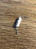
Fusistor open on function board! Explains the dodgy track? The track has continuity. Should I replace all fusistors? I am thinking why now, must have happened recently, or just bad karma. ;-)
 

Attachments

  • track.jpg
    track.jpg
    127.7 KB · Views: 16
  • fusistor.jpg
    fusistor.jpg
    187.6 KB · Views: 15
Should be 2 fusibles on the function board, one each for the phono and mic
power supplies. Going open suggests a downstream short which you will need
to track down, which FR40x? Was the fusible in spec after the refurb, all
fusibles should be checked and replace any that are out of spec.

Still looks like 2 problems, a short somewhere and lost GND connection.
Regarding the GND issue.

There should be continuity between any black speaker post and the front
connector on the function board, the clear insulated wire, pin 2 counting
from right.

If ok, then slide function board forward and unplug large connector and again
check for continuity between black speaker post and each clear insulated (middle)
wire.

upload_2020-11-14_8-39-8.png

If that's ok then you need to inspect the rear panel/RCA board. Remove screws and
tilt down, check black wire secured to chassis.
 
Last edited:
Thanks! 47 Ohm fusible was open, but was within specs before. Of course I did check earlier. I read thread of jd3rdcoast (CA-1000 Revisiting...) and feared your responds. Will replace the fusible with the Vishay's you recommended. The 220 Ohm also. Tested the coupling switch (ok) but will try to take it apart and clean it. Still puzzled what happened. Never touched the rear panel. Burnt tracks at the RCA connectors? Your suggestions are clear! For now to bed and weekend. BTW could the MC-board have triggered the 47 Ohm to get open? I did a recap and replaced the outhouses just before trying to wrap things up. Did check position trannies.
 
47 Ohm fusible was open
I assumed the fusible was on the function board (100, 220ohms). 47ohm on the relay board (underneath), confirm 47 ohm
on relay board.

When you have time, check continuity as per post #218.
Probably need a full list of what the last things you changed out.
 
I assumed the fusible was on the function board (100, 220ohms). 47ohm on the relay board (underneath), confirm 47 ohm
on relay board.

When you have time, check continuity as per post #218.
Probably need a full list of what the last things you changed out.
47 ohm (100mA) ! and 220 ohm (45mA) on function board. See pics
 

Attachments

  • IMG_1340.jpg
    IMG_1340.jpg
    130.2 KB · Views: 20
  • IMG_1339 2.jpg
    IMG_1339 2.jpg
    135.2 KB · Views: 19
Back
Top Bottom