• The move to the new server is done. There are some software and database maintenance updates in process. This has us passing the hat around to help out. We appreciate any donations. Seriously, even a dollar helps. The payment page may be found here - https://www.audiokarma.org/support.html

Advice requested on repair Yamaha CA-1000

Dis-reguard what happens when playing audio, amplified signal passes these test points (TP3,TP4) which
affects the voltages at these TP's so it may look like unstable bias. Check bias as per service manual, what
you've said in the past may indicate intermittent/failing silicon, solder connections or ... dunno. Try to work
out which half (top/positive or bottom/negative) is causing the problem.
EDIT: do not expect the bias to remain constant, I did some measurement on one amp
and saw a gradual drop from 940mV down to 890mV over 45min, while not ideal I wasn't
greatly concerned, possibly due to the different Vbe of orignal/replacement TR606.
You mentioned swings upto 1.2V, this would concern me.
 
Last edited:
Dis-reguard what happens when playing audio, amplified signal passes these test points (TP3,TP4) which
affects the voltages at these TP's so it may look like unstable bias. Check bias as per service manual, what
you've said in the past may indicate intermittent/failing silicon, solder connections or ... dunno. Try to work
out which half (top/positive or bottom/negative) is causing the problem.
EDIT: do not expect the bias to remain constant, I did some measurement on one amp
and saw a gradual drop from 940mV down to 890mV over 45min, while not ideal I wasn't
greatly concerned, possibly due to the different Vbe of orignal/replacement TR606.
You mentioned swings upto 1.2V, this would concern me.
I do understand the impact on the bias while playing music. Fluctuation is normal then, I do take that in account. It's interesting to see what happens to it in loud passages for instance. That 1.2V is really true. In a stable phase I adjusted to 940mV, than all of a sudden it went besurk. From 0,84 - 1,2vdc. What you mean by "which half (top/positive or bottom/negative) is causing the problem" is a bit harder to grasp. How does it help me to pin-point the problem? Furthermore am I correctly thinking when I say that in normal-mode TR606 does not have much to do, while the heatsink hardly gets warm, but in class A all the more, because the heatsink then gets very hot and has the purpose of preventing the bias from running away. That would explain while there are no problems in normal-mode. If all else fails I could replace all diodes (in stock) and TR604/605, even for TR601 I have a new one (NOS). Finally I really, really appreciate your patience and of all the others who are helping me with suggestions. I seem slow, but I just like conformation sometimes.
 
In basic terms, the power amp has positive and negative rails and
the speaker line/output midway between them. Driver/output transistors
connected to the positive rail construct the positive half of the audio
signal, same applies to the negative rails/driver/outputs. The positive
and negative waveforms are combined at the speaker line, maybe this helps,
upload_2020-2-12_6-44-32.png

Knowing which TP is drifting/swinging points to transistors etc... on
that half of the amp.
 
In basic terms, the power amp has positive and negative rails and
the speaker line/output midway between them. Driver/output transistors
connected to the positive rail construct the positive half of the audio
signal, same applies to the negative rails/driver/outputs. The positive
and negative waveforms are combined at the speaker line, maybe this helps,
View attachment 1760457

Knowing which TP is drifting/swinging points to transistors etc... on
that half of the amp.
I know the basics of push-pull amplification, but would never have thought of tackling the problem in this way. Should I look where the jumping of voltages is the most significant, positive or negative rail? TP+ and - against E? Right?
 
Right. I would try, I'm not saying it's going to work, it takes like 2 seconds so I would try, generally try anything
that may localise the problem. If it doesn't work then try something else...
EDIT:Refining the test a little...
Keeping in mind that the power is coming from the unregulated supply so voltages will
bounce around a little... Try with 2 multimeters, one to measure the bias at the TP's and
one to measure the Vdc between TP and GND. When the bias bounces wildly check which
TP voltage has the bigger swing.
 
Last edited:
Right. I would try, I'm not saying it's going to work, it takes like 2 seconds so I would try, generally try anything
that may localise the problem. If it doesn't work then try something else...
EDIT:Refining the test a little...
Keeping in mind that the power is coming from the unregulated supply so voltages will
bounce around a little... Try with 2 multimeters, one to measure the bias at the TP's and
one to measure the Vdc between TP and GND. When the bias bounces wildly check which
TP voltage has the bigger swing.
bias.jpg TP +.jpg TP -.jpg
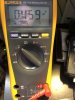
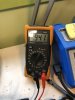
Here my findings. Any conclusions? No big difference between + and - in swing during 'jumping time'. Pictures made during stable situation.
 

Attachments

  • TP +.jpg
    TP +.jpg
    47.9 KB · Views: 6
  • TP -.jpg
    TP -.jpg
    46.2 KB · Views: 6
  • bias.jpg
    bias.jpg
    45.3 KB · Views: 6
Yeah, nothing to see there. Really need to capture the bias bouncing around, like the 1.2V previously mentioned
then check TP voltages. Again, this may show nothing. Maybe a very very short shot of freeze spray on suspect transistors
may help. You only want to "tickle" the transistor, too long a sproy will shut it down and throw the bias out of kilter...

Thanks for all your help. It was the mechanical part of the mode switch after all. Moving on to the next step.
 
  • Like
Reactions: mbz
I moved on to the next step and I am restoring/recapping the functionboard. I noticed that I have a different version or layout than on the schematic. I have LC63792 (NA-06582) the schematic says LC62854(NA-06335). Can any of you point me in the direction of the version I need? Or am I mistaken?
 
The function board on most of the CA-1000's out there are the different version than the service manual.Just have to "deal " with it.
 
I noticed that I have a different version or layout than on the schematic. I have LC63792 (NA-06582) the schematic says LC62854(NA-06335).
Schematic corresponds to early releases for japanese domestic market. You have the updated/improved version, changes
are not so great, 1 or 2 of the larger caps, 1 FR? and possibly different ground path, early version was prone to burning a track
(at short). Sketch the board layout showing parts/orientation of caps, transistors,,, you are considering replacing.

Here some pictures of my board. I replaced the elec-caps with first grade Vishay's. The big UCC's not yet. I was a bit confused because I could not find the caps in the manual on the board. Some 100uF/10 caps. My intention is to replace the tantals as far as there is enough space with audiograde elco's/wima's, as avionic suggested in some other thread in here. Furthermore the 'outhouses' with black connections, once more I will follow the replacement suggestions of avionic in other threads. I will leave those red-dotted fet's alone, the green one's also, although I believe I have some NOS in stock. The filtercaps I will replace with mbz's suggestion UCC 85 degree, because of the three leads (no drilling etc.) just cut one leg ;-)
The board layout is no problem, my HAKKO desoldering pistol is doing a great job. A very short suck and the parts almost fall out. Is this strategy ok?

IMG_1125.jpeg IMG_1124.jpeg
 
Here some pictures of my board. I replaced the elec-caps with first grade Vishay's. The big UCC's not yet. I was a bit confused because I could not find the caps in the manual on the board. Some 100uF/10 caps. My intention is to replace the tantals as far as there is enough space with audiograde elco's/wima's, as avionic suggested in some other thread in here. Furthermore the 'outhouses' with black connections, once more I will follow the replacement suggestions of avionic in other threads. I will leave those red-dotted fet's alone, the green one's also, although I believe I have some NOS in stock. The filtercaps I will replace with mbz's suggestion UCC 85 degree, because of the three leads (no drilling etc.) just cut one leg ;-)
The board layout is no problem, my HAKKO desoldering pistol is doing a great job. A very short suck and the parts almost fall out. Is this strategy ok?

View attachment 1858165 View attachment 1858166
Those two slide switches need to be removed,disassembled and properly cleaned.. Guarantee they are filthy with black tarnished contacts just like the example below.
index.php
index.php
 
I know and I totally agree, but if those tiny clips break off when they are bent open just a little bit too much, you are f***ed. I'll be honest, when I restored my first amp a Yamaha A560, I had these switches cleaned in Germany http://www.good-old-hifi.de. They are experts and do it all the time, but it was rather expensive, you are an expert, I am not. Shaky hands etc. No replacement possible, because they are unobtainable. I am going to practice on old gear first before acting, for now a little bit of Deoxit. I know your suggestion is the best thing to do. Don't get me wrong.
 
, for now a little bit of Deoxit. I know your suggestion is the best thing to do. Don't get me wrong.
You can't get the deox-it in where it will do any good.Because of the plastic slider pockets.
 
Certainly the switches will be dirty however are they causing attenuated or lost channel, deep cleaning is the only solution
in this case. Recently I've had problems with the Bass Turnover Switch in the Defeat position. Those sliders are very easy
to bend out of shape then your also forked. You might get a bit of spray in if the end is open and you spray parallel to the board
aiming for the metal tracks and groove as per blue pointer. Stand board vertically, spray down and work switch, however this is hit
and miss.
upload_2020-5-8_18-45-14.png
 
Those sliders getting out of shape is another thing, horror! But just suppose I desolder them and try to spray them from below more thoroughly, is that an option? Or put them in an ultrasonic bath, I have got one.
 
The white plastic encases the sliders and tracks. The only opening I can see is the blue arrow as indicated. Remove the board
leaving the switch attached then try spraying on the rails... Not sure what effect ultrasonics would have on the plastic case.
Wait for someone to chime in.
 
Reading Wiki... the ultrasonics acts as a agitator for the solvent, this agitation does heat up the solvent somewhat so don't
use a flammable solvent. Apart from that it comes down to the choice of solvent, something that wont attack the plastic...
Water alone wouldn't be a good choice.
 
Back
Top Bottom