• Please note that Audiokarma will be offline briefly for updates early on Monday morning, September 28th.

AK Design Collaborative - Insignia-Class Economy Speakers (a.k.a Indignia)

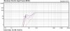
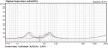
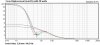
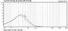
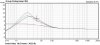
What is the power handling of the Indignias and how much is given up by building a larger cabinet?
It depends on where we tune it:

attachment.php


attachment.php

1) Grey and Orange are closed box, 0.5 and 0.38 cuft respectively, for reference.

2) Green is the standard Indignia alignment - 0.38 cuft, 1.5" x 8" duct, Fb = 38.16 Hz, F6 = 41.08 Hz, 30.1 W

3) Violet is the same but 0.5 cuft, 1.5" x 8" duct, Fb = 32.86 Hz, F6 = 36.52 Hz, 15.6W

4) Black is the 0.5 cuft box retuned to standard Indignia tuning, 1.5" x 5.502", Fb = 38.16 Hz, F6 = 36.52 Hz, 18.3W

Note: Green and black max input power curves superimpose. At any given frequency, with the same box tuning, the maximum input power capacity is equal in the 0.38 and 0.5 cuft box sizes.

If we tune it the same, it will play lower (F6) with the same power handling capacity.

More curves below.

Verify....
 

Attachments

  • BB6P CAR.JPG
    BB6P CAR.JPG
    37.1 KB · Views: 275
  • BB6P MEP.JPG
    BB6P MEP.JPG
    35.6 KB · Views: 270
  • BB6P IMP.JPG
    BB6P IMP.JPG
    35.3 KB · Views: 15
  • BB6P CD.JPG
    BB6P CD.JPG
    35.7 KB · Views: 15
  • BB6P VV.JPG
    BB6P VV.JPG
    34.8 KB · Views: 10
  • BB6P GD.JPG
    BB6P GD.JPG
    34.8 KB · Views: 11
Last edited:
Wow, It's been a while since I've been on this thread, but I am finally starting to build my set of Indignias out of cherry wood.
I know a guy with a CNC machine, who is going to cut the baffle holes and flange areas for me. For me that's an easier option than drilling and cutting them myself, due to my lack of tools.

Anyone else want their baffles machined?
I know half of the fun is doing everything yourself, but I thought I would just throw that out there. If there is any interest, I can get a price quote, etc.

Also, I notice that some of you choose ported and some choose non-ported.
I would love to hear a couple opinions on why people choose one over the other.
I realize it's personal taste, etc etc, but I am not familiar enough to know what my taste would be.

I guess I did hear someone mention "zilch plugs"... I don't know what the deal is with Search, but I can't find any posts on it. eh?

Thanks
Andy
 
Wow, It's been a while since I've been on this thread, but I am finally starting to build my set of Indignias out of cherry wood.
I know a guy with a CNC machine, who is going to cut the baffle holes and flange areas for me. For me that's an easier option than drilling and cutting them myself, due to my lack of tools.

Anyone else want their baffles machined?
I know half of the fun is doing everything yourself, but I thought I would just throw that out there. If there is any interest, I can get a price quote, etc.

Also, I notice that some of you choose ported and some choose non-ported.
I would love to hear a couple opinions on why people choose one over the other.
I realize it's personal taste, etc etc, but I am not familiar enough to know what my taste would be.

I guess I did hear someone mention "zilch plugs"... I don't know what the deal is with Search, but I can't find any posts on it. eh?

Thanks
Andy

Zilch plugs are available at home depot, lowes, or any place that has plumbing supplies. They are plummers test plugs, and come in various diameters. Put in vent, turn screw which expands the middle, plugging the port hole.

Russellc
 
"Metal screen." ??

It comes in all different combinations of hole size and spacing. When I asked what sizes worked the best, he replied: "It's a matter of testing and trial and error.". So, he ain't giving up everything!:no:

But, I've got some ideas bouncing around in my head, based on the screens on the Snells.

I happened to surf the Snell site before I read your post and was surprised to see the mesh grills. Now that you've confirmed it, and I think about all the small speakers I've seen recently, it's like a light bulb went on.

It's been around for a few years now, but it always seemed like it was the lower-end speakers that sported metal grills. Now it seems like maybe they have been on to something. I'm going to compare the hole sizes on some of the ones I have here and see if they're all the same. Maybe there's a common size. :scratch2:

If they are as good or better than fabric acoustically, they would have a huge advantage in physical protection over fabric.

Maybe some AKers with test equipment and some mesh material lying around will do some quick tests... :yes:
 
Some pretty decent speakers in the past came with perforated metal grilles.

Minimus 7s and various models of ADS come to mind.
 
I've been listening to mine in the downstairs system, turntable ( in sig) to an AVA Super Pass III, to a DIY P-P 6550/KT88 amp and indignias. Its taken a little time to aclimate to them, having been used to much larger higher efficiency speakers. They are located in a room that normally where my A7s are, so it may be a little large. I have them closer together than the A7s, and sitting position is much closer.

Like many have already said, they have mini monitor imaging, which is a good thing. Measuring with a rat shack sound level meter, they seem to play best in the mid to high 80 db zone. This is at the listening position, by the way.
When increased to the 90's, they begin to show some strain. Again, the room is a little large for these personal scale speakers. Also, this is with a turntable which with these speakers there is a little woofer dance, so may be cleaner at higher volumes with cds, or utilizing a subsonic filter. I am currently listening to a few disc that I am very familiar with, to get a good working knowledge and familiarity with their sound. Once this is done, I got some comparing to do!

I have two speakers, both DIY projects I intend to make the comparisons with. First is a very similar speaker in terms of cubic feet, my clone of the JM Labs Micron. I built these after a very favorable review done by Stereophile
in the 90's. The review revealed the Cu Ft of the box, as well as the tuning frequency. Also revealed was th emodel number of the focal drivers that were used. At the time, Focal sold these drivers to the DIY crowd, but has since severly limited what it sells part wise. Kimon from Focal America was kind enough to send me the crossover schematic. A friend and I constructed boxes from a double layer of 1/2 mdf, and they are bi wireable. Tweeter is a one inch inverted dome, with titanium dome. The woofer is a double voice coil 5 1/4 inch driver, cone is made of neoflex.

These drivers were considerably more expensive than those used in Indignia,
but I dont anticipate that Indignia and its less expensive drivers will be embarrassed by any stretch. anywho, I think it will make for an interesting comparison.

The second comparison speaker is another a DIY effort from the 90's, the Aria 5. This is a design of Joseph Diappolito, and also uses two focal mid woofers and a one inch titanium inverted dome tweeter, but this is a slightly newer driver than the one in the Micron clone. Its dome is treated with titanium dioxide, which leaves it a dark grey/black color. It also has some sort of a small lens in front of the dome. The woofers are 2 to the side, in "Diappolito" alignment. The woofers have kevlar cones, and are also 5 1/4 inch in diameter. Again, these are considerably more expensive drivers than used in the Indignia, and it will also be a good comparison for a little more upscale (pricewise) speaker.

The Aria 5 speakers are usually positioned to either side of my flat screen, so are in constant use. The microns dont see that much use, so will need to be "broken in" just a little.

What do I anticipate? I think Indignia is not going to be embarrased in this comparison at all. Performance between Indignia and Micron should be similar, Micron may take higher power a little more gracefully, but we will see.

The Aria will be a little more intense of a comparison, and a little less fair. While Indignia was less than 300 in 2009 dollars, I spent in the neighborhood of 850 1990's dollars building the Arias. Plus, with its double woofers, dynamics are very well handled. I think a Diappolito alignment with dual 6 1/2 inch Dayton aluminum drivers would be a little more fair. Anyway, the comparo is on.

I also plan to bring Indignia to Jaymana's June bash, so hopefully a few more opinions will be forth coming. Stay tuned!:thmbsp:

russellc

Preliminary testing sort of eliminates the Aria 5 from this comparison. Two drivers simply gives more dynamics than one. The Aria would be a better comparison to a dappolito arrangement, 2 of the little aluminum drivers would give some serious competition. The Indignia is just as pleasant to listen to small scale, but when the powers up the Arias are able to pressurize this room
and sound large even at higher volumes.

The micron clone is a much closer comparison, which continued last night......sort of......Note to self, when critically listening and wondering what is slightly off, make sure pre isnt set to "mono" :D Pictures to follow of these speakers/speaker being compared. First impressions are the Indignia compares very well, with considerable less expensive drivers. It sounds slightly drier ( not meant as a criticism here) than the micron, which is a little richer. This is primarily noticeable at louder levels. The Micron, with its more expensive drivers, handles power at higher levels a little better. In terms of Imaging, both are champs. Both are fairly fatigue free long term listening, with the Indignia being perhaps slightly more listenable long term, as long as the volume is reasonable. The Micron holds together a little better when attempting to get loud, and while it bests the Indignia in this regard, neither are a rock the house speaker.

Next, everthing moved upstairs, perched on top of the 4507 boxes. The downstairs room is a larger room, which is of course a little more difficult for a small speaker to play into. Upstairs is a little more intimate, and much more friendly to these smaller speakers. Some of the dryness I noted in the INdignia downstairs was improved. The speakers were really shining now!

Switching out to the Microns also showed a similar benefit over the larger downstairs room. Very close race. My friend with whom I built the Micron clones recently had a voice coil go out, ( or hopefully some connection) on his set of microns. since the drivers are no longer available, he is considering options, to which I have quickly recommended Indignia. The only real advantage the micron holds is its ability to make use of a little more power and volume. At lower level listening, its a virtual standoff, each with its faults and benefits. Talking about power levels, one thing I noticed was these Indignias REALLY can soak up some power! A big Indignia advantage is the relative inexpensive nature of the drivers. Easily replaceable, unlike the Focal drivers, and cheap! Blown woofer like my friend has could be fixed for about 25.00.....new driver! Huge advantage Indignia!


Russellc
 
Last edited:
Working on the first one today! (I'm building one by myself this weekend to figure everything out so that when I bring my son into it, I'll 'know' what I'm doing!)

All assembled and no sound out of either driver. Pictures would help I know but here's a few points about my install.

1. I'm new to soldering, could the PC board gotten too hot and 'burned' any of the connections away? The flux I used left a dark greasy residue but maybe I effectively burned something? Don't think so but it's my first PCB work.
2. Going back through every connection, to see if it's tight, but I don't have any type of multimeter to see if connectivity is made...
3. I guess I mounted my PCB 'upside down' because the positive ended up on the left outside the back of the speaker. Thankfully, going slow without any distractions I caught the reversal before testing. I didn't consider that when I choose the orientation of the PCB - only that the LF + and - was down lower and the HF + and - were up higher.
4. LF stands for low frequency and HF stands for High Frequency yes? lol. hope so otherwise we gotta talk about naming conventions...
5. I terminated the binding posts working from outside the cabinet in just as Zilch described in detail with the lock washers, etc., and it appears that each binding post sits inside a separate circuit on the PCB - effectively + and -. But right next to each binding post is a small hole for soldering a wire to. For what? I never saw that wire on Zilch's example PCB. Maybe that's a redundant offering? Anyway, I'm not using them - is that my problem?

Where can I start - although I'm already going through it as I write this?

Anyone care to offer thoughts?

thanks
peter
 
Where can I start - although I'm already going through it as I write this?

Anyone care to offer thoughts?
1. Flux does leave a residue.

2. Multimeter would help, yes.

3. Input polarity would not prevent the system functioning. Just swap the thumbnutz. Let's see some pics.

4. Yes, LF is woofer, HF is tweeter.

5. The spare holes are for those mounting the input terminals separately, as in a terminal cup, and wiring them to the board, instead of connecting the terminals directly.

Perhaps your son can figure out what's up.... ;)
 
Last edited:
Made a foray to Zilchlab today to pick up the chokes for my Indignias and got some great insight on speaker building from Zilch:

Wanted to pass along my many Thanks...:thmbsp:
 
OK so I'm home with my brand spanking new 29 Range Digital Multimeter.

Have to pull the XO out of the box to fully test the individual components...

what am I testing, and how am I testing? lol. that sounds ridiculously ignorant. But after I monkey with a few things and figure out the signal path I won't really know what values to look for.

wish me luck or if anyone's got anything to add...

peter
 
With everything connected, but no amp, what's the DC resistance across the input terminals?

Then.... make sure you have zero ohms resistance from component to component in the signal path.

Then, ground to ground to ground... all should be zero.
 
Thanks guys!

Here's what I've found using the multimeter.

1. Set the meter to Ohms (confirming the obvious - Omega greek symbol).
2. tested binding posts on outside of box. either way no measurement was made. Telling me no completed circuit I'd guess.
3. Removed XO from cabinet (mental note to self for next time - test drivers BEFORE painstakingly installing XO. lol.)
4. With both drivers connected
5. Each individual component tests 0.00x on the ohms, x being as large as 8. 8 thousandths is zero in my book. And I first tested the wires ABOVE the solder and verified I should get a zero on the solder - and to basically figure out how the meter works! hehehe.
6. Touching both sides of the binding post holes yields the same zero resistance reading.....

ahah. interesting because when I tested them using the posts themselves (first test before removing the XO, on the outside of the box.) yielded an Of reading - meaning NOT zero on the meter.

7. Speaker leads also read zero across + and -.

8. Starting at one end and working across all combinations of solder yields similar 0.00X results.

So tell me, how does one connect binding posts?!?! Or did I miss something?
 
Completed and working Indignia measures 6.3 Ohms here.

What's your woofer measure across its terminals with the crossover not connected?

With the drivers connected, you should read the same ~6.3 Ohms as me across the input terminal pads on the solder side of the board.

That's where the input terminals must make contact, and I believe I outlined a mounting procedure which accomplishes that.

Have you found that in this thread? Is that what you're following? Link us to that post, please.

Again, some pics would help so we can see what's up with what you've done....
 
Zilch,
Thanks.

update -SKIP THIS MESSAGE - I think I found the problem.

I'll leave the msg below in case I'm not correct!
peter
_____-----------__________----------


Tried both drivers unconnected. Yielded 5.9 on the woofer, 6.1 on tweeter. Then with fastons connected both gave similar readings - don't know what I saw or tested for before - this meter takes a few seconds to recognize a signal - and maybe I wasn't waiting long enough before...sorry.


The post I used to construct the entire XO was post #939, on or around p63. My XO looks very similar to the pics - same solder points, location, amount, etc. On the top all the daytons are lined up as yours are - text going in the same direction. Resistor is spaced. What about that copper coil - was there a direction on that? All I did was set it so the wires were coming off that end to make a straighter run. Couldn't see yours in the photo.

So sorry but no photos. My wife and kids took it with them this weekend. But my pics look like yours! Kind of.

thanks
peter


Yes, this is the place! :thmbsp:


attachment.php


attachment.php

Notes:

a) Production boards have green solder mask making the soldering easier and neater.

b) They also have an overlay on the component side with parts designations and input/output polarities.

c) Driver leads get terminated with 1/4" Faston connectors; the holes are sized to accept 18 ga. wire.

d) If you mount the 1.5 mH I-Core inductor using #4-40 (x 3/8" - 1/2" length) hardware, the nuts can go on the component side. Use #4 flat washers, too, as the inductor mounting frame is plastic, not metal. I use nylon insert locknuts, as shown.

e) You'll likely have to scrape the enamel off the I-Core inductor leads where they pass through the board. A utility knife will do it easily; you want clean copper there for the soldering.

f) Pads of 3M double-sided foam tape cushion and secure the capacitors and the small inductor to the board. It's white and comes in 1/2" and 3/4" width small rolls from the local ACE hardware. I don't use it on the resistor, but stand that ~1/32" off the surface so air can pass between it and the board. I solder that on first with a credit card as spacer, which I remove to proceed with installing the other components.

g) Input binding posts press in from the outside through the holes provided on the rear of the PE cabinets. If you pound them in, remove the thumbnuts and cushion with a piece of scrap wood. Pay attention to the orientation of the wire feedthroughs when doing this; the knurled section locks it to prevent rotation when you install the hardware on the inside. A phillips screwdriver through the hole in the binding post will assist in lining it up accurately.

h) The hardware sequence is: binding post, cabinet wall, solder lug (provided) as washer, hex nut, toothed lockwasher, PC board, toothed lockwasher, hex nut. This secures the board and stands it ~3/16" - 1/4" off the inside of the rear panel.

i) The binding post hex nuts tighten with a 10mm socket, or, if you do it carefully so as not to damage the nearby components, long-nose pliars.

j) Secure the board from the inside at its four corner locations with nylon standoffs and wood screws of the appropriate size and length, also available at ACE. Alternatively, you can make standoffs easily by parting off the required lengths of aluminum, brass, or plastic tubing from ACE with a hacksaw. You may need a stubby screwdriver to drive the two behind the cabinet brace. I just use short (3/4" - 1") sheetrock or deck screws, as no pilot hole is required for those.

k) 1" thick fiberglass insulation is available as duct wrap at home improvement centers; I use black plenum liner from the local HVAC sheet metal fabrication shop for Indignia cabinet damping.

 
Last edited:
GOT IT!

I think my nylon spacer behind the XO was standing slightly (!) proud of the adjacent nut/lock washer assembly - but enough to prevent that lock washer from carrying the signal to the PCB!!!!!

AHHHHHHHHHhhhhhaaaaaahhhhhaaaaa.

Woooohooooo!

Tell me this. Can I safely mount the second set of binding posts (not set in the other cab yet) to the PCB and test them with a receiver before putting everthing back in the box?

thank you thank you thank you,
peter
 
Back
Top Bottom