• The move to the new server is done. There are some software and database maintenance updates in process. This has us passing the hat around to help out. We appreciate any donations. Seriously, even a dollar helps. The payment page may be found here - https://www.audiokarma.org/support.html

Altec 846B Valencia restoration next steps

holger7188

Member
Recently I have acquired a pair of Altec 846B Valencias and my plan is to restore and use them as my main speakers. I am now thinking about how to proceed with the restoration and am hoping for a few pointers. The original owner said he bought the speakers 50 years ago and didn’t do any maintenance on them since.

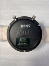
The 806-8A compression drivers did not work – the tinsel lead was broken. I soldered the lead and now they are working again.

However, while repairing the drivers I noticed that the Alnico magnet appears to be weak. I have no experiences with these kind of drivers or Alnico magnets… is there a way to tell whether the magnet is as strong as it should be or if it needs to be remagnetized?

One way to describe it is that a small screw barely sticks to the outside of the driver (at the seam between the magnet (?) and the part that connects to the horn). And I paid attention to be careful about the magnetic pull of metal tools into the membrane, to avoid damaging it, but I didn’t really notice any magnetic pull, at least not around the tinsel lead area – which makes me worried that the magnet is not as strong as it should be.


Other repairs I wanted to tackle, please let me know if it makes sense or not:

- I already rotated the 416-8A woofers 180 degrees

- the black painted glass wool dampening around the horn is in bad shape and needs replacement, not sure what to replace it with yet
- I want to replace the glass wool dampening inside the speakers as well, since I had to rough it up in a few places and probably set a bunch of fibers free, plus I have a small kid at home and don’t want to risk the health hazards involved with old glass wool. Possible replacement: rock wool?

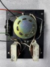
- The crossover seems o.k. – for its age. I haven’t desoldered and measured the single components yet. Seems like it could benefit from an update, though, so I’m considering to re-build the same design with new components for now. I have read that another crossover design would be better, but the idea is to listen to the speaker the way it was planned/released first, before doing design updates.

- Cosmetic repairs like making the wood look good again, cleaning, maybe updating the cover.

- anything else? :-)
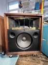

IMG_5044.jpeg
IMG_5099.jpeg
IMG_5127.jpeg
IMG_5083.jpeg
 
Register to hide this ad
Nice. I don't know how to measure them without an expensive Gauss meter, but Great Plains Audio will recharge them for 30 bucks a pop. Just had a couple drivers recharged last week. Seems like the magnet should draw quite a bit. After you listen to them, you might update to a Zilch Model 19 crossover and take them up a notch. I think that's what I've read. or maybe it's a Markwart. Either should be good. Post your results.
 
Nice. I don't know how to measure them without an expensive Gauss meter, but Great Plains Audio will recharge them for 30 bucks a pop. Just had a couple drivers recharged last week. Seems like the magnet should draw quite a bit.

Thank you for the input. Did you hear a big difference after having them recharged? I've heard many great things about GPA and would send them in for recharging. Problem is: I'm in Europe, and while I have found a speaker repair shop who does recharging, I 1) have no idea if they do a good job, and 2) they charge way more for that than GPA does, and I'm not willing yet to commit to such an expense if I'm not sure that the drivers would benefit greatly from it.
 
One way to describe it is that a small screw barely sticks to the outside of the driver
Perfectly normal.

By nature of it's construction, an Altec alnico driver is magnetically shielded.

You should only detect strong magnetic pull near the gap, and it's best not to tempt it as the field becomes exponentially stronger as you get closer to it. There's no safe way to feel the pull while a diaphragm is in place.
 
Alnico magnets slowly lose a very little magnetism over many decades or centuries. Unless they have been extraordinarily Heated , which highly unlikely. Or hammered on, like being dropped very hard. You would probably see physical damage in that case.

I once spoke to Bill Hanuschak at Great plains and he told me the same. Your driver are probably fine.
 
Thank you for the input. Did you hear a big difference after having them recharged?
The 515 isn't built yet. I had it charged because of it's unknown origin and didn't want to take a chance for such a small fee. The other compression driver was only a little low according to Bill, so there was no difference.
 
Thank you guys, that’s reassuring!

This leaves the dampening and the crossover as the biggest “issues” to tackle.

Any idea what material might be best to replace the glass wool around the horn? I’d use rock wool, but then I’m not sure how I’d make it look pretty for when the speaker cover is off.
 
I would replace the Capacitors only in your crossover. I would use Film capacitors. I have tested quite a few of those brand of Crossover caps and they all were way off spec. They were probably good quality when new, but the age has most probably deteriorated them. Clean and lube the control pot. I would use Deoxit or the equivalent.
 
I would replace the Capacitors only in your crossover. I would use Film capacitors. […] Clean and lube the control pot. I would use Deoxit or the equivalent.

Alright will do, sounds easy enough. The inductors look pretty shabby and I have no tools to measure them, but you’re right: I don’t see why they wouldn’t work as they did 50 years ago.
 
So, I opened and checked out the 2nd speaker last night, and soldered the broken tinsel lead (?) in the high frequency driver back together. The horn works again for now and it’s the first time I hear the Valencias in stereo. I was quite surprised by how the speakers acoustically disappear and the sound appears to come out of nowhere.

Anyway, I noticed the 2nd speaker had a 180 degrees rotated woofer compared to the first one. The binding posts for the cables from the crossover were pointing down, whereas for the other woofer they were pointing up. Does anyone know how they came from the factory, with binding posts facing up or down? (both compression drivers’ posts were facing down).

The dampening tape between horn and chassis was missing on the 2nd speaker, too, and the wood screws that attach the mounted woofer to the chassis were overtightened, so I assume this one had been opened previously for some reason or other.
 
Anyway, I noticed the 2nd speaker had a 180 degrees rotated woofer compared to the first one. The binding posts for the cables from the crossover were pointing down, whereas for the other woofer they were pointing up. Does anyone know how they came from the factory, with binding posts facing up or down? (both compression drivers’ posts were facing down).
One may have been flipped over to alleviate cone sag. You may find that if you put it back, the voice coil rubs. OTOH, sometimes they are flipped if the surround dope is starting to "run" into the cone.
 
One may have been flipped over to alleviate cone sag.
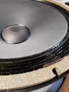
Yeah I assume that’s the only plausible reason why someone opened the chassis… dope looks symmetrical on this one, too – very unlike the first speaker in which I flipped the woofer just for this reason (photo attached). The amber colored gooey stuff was already partly about to leave the woofer behind altogether. I cut the protruding piece off and flipped it.

IMG_5087.jpeg
 
250VDC rating is fine. Some mfd values are only available in 630VDC ratings. Those work, but I've found that they may need a little longer to fully break-in.
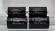
Actually I have one more question about the Solen caps: I'm looking at values now, and since there's no 8uF cap, would you use 2x 3.9uF, or the 8.2uF one, or...?
Same for the 21uF one: substitute with 1x 22uF? 18uF + 2.7uF?

Reading up on this online makes one’s (mine at least) head spin, because eventually the discussion goes to ESR and how you have to compensate for it when you use a film cap instead of the original electrolytical one, yada yada.
 
Reading up on this online makes one’s (mine at least) head spin, because eventually the discussion goes to ESR and how you have to compensate for it when you use a film cap instead of the original electrolytical one, yada yada.
For many(most) enthusiasts this is splitting the fine hairs beyond the point of diminishing returns.

would you use 2x 3.9uF, or the 8.2uF one, or...?
Same for the 21uF one: substitute with 1x 22uF? 18uF + 2.7uF?
Pick your preference.

Economics aside, if i have to parallel multiple caps to arrive at a desired value, it's my preference that they all be caps of equal value.

Also, consider that the original components had a 10% tolerance at best.
 
Last edited:
thank you – again – for easing my mind. I’ll also assume +/- 1uF won’t matter on the bigger cap.

Will keep you posted (hope this doesn’t sound like a threat by now!)
 
Back
Top Bottom