

You are using an out of date browser. It may not display this or other websites correctly.
You should upgrade or use an alternative browser.
You should upgrade or use an alternative browser.
Altec 846B Valencia restoration next steps
- Thread starter holger7188
- Start date


What I would do is run the crossover schematic through a crossover simulator program and find what's ideal for the the impedience and choke, and if it is less than the value that was used (i.e., 8 mfd and 20 mfd), use the closer value/pair that is less than the value used. Similarly, if the program says to use a bigger cap, go to the next size up.Actually I have one more question about the Solen caps: I'm looking at values now, and since there's no 8uF cap, would you use 2x 3.9uF, or the 8.2uF one, or...?
Same for the 21uF one: substitute with 1x 22uF? 18uF + 2.7uF?
Reading up on this online makes one’s (mine at least) head spin, because eventually the discussion goes to ESR and how you have to compensate for it when you use a film cap instead of the original electrolytical one, yada yada.
I would bet that when the original crossovers were designed, they didn't have the sophisticated computer programs to obtain the ideal slope, in the blink of an eye. And, I would think that they were also restricted by what the vendors could supply at the time and what the bean counters would allow. ("What, you want to use twice the number of caps just to add 0.2 mfd to get the perfect value? No way!")

holger7188
Member
What I would do is run the crossover schematic through a crossover simulator program and find what's ideal for the the impedience and choke, and if it is less than the value that was used (i.e., 8 mfd and 20 mfd), use the closer value/pair that is less than the value used. Similarly, if the program says to use a bigger cap, go to the next size up.
That’s a great idea. Just had a look for simulation programs, but there seem to be few for Mac, and the free online simulator I found (this one) gives me the same capacitor values for both, no matter which simulation model I choose (with 8 Ohm for each driver and 800Hz as input values), so that’s obviously different from the schematic.
Might have another look later, but to save me a headache I might just ballpark it and/or use a few good caps I found last night to save money (4.7+2.7+0.47=7.87uF – should work for the 8uF one?)
Cheers!
bowtie427ss
Lunatic Member
What Mr Todd hasn't told you is that you will need the impedance curves for your drivers, or at the minimum you need to know their measured impedance at the intended crossover frequency.That’s a great idea.
You cannot just plug nominal impedance values into simulation software and expect to produce results of any use or accuracy.
Altec engineers knew exactly what they were doing when they chose the cap values.
The overlap is there for a reason, in part to avoid the necessity of a Zobel.
Some people really think audio was in the dark ages until they saw a PC modeling program with their own eyes.
Maybe in another century we can convince those faithful that ALL modeling programs provide you with an estimation at best.
For the history buffs, CALSOD 2.00 was released in ~1990, it was on 2 floppy discs, and i think it cost me about 65 bucks.
bowtie427ss
Lunatic Member
Should work, does not equal ideal.(4.7+2.7+0.47=7.87uF – should work for the 8uF one?)
.47 will probably act as a VHF by-pass, if it has a very low ESR it might help add a teeny touch of sparkle on top.
holger7188
Member
Should work, does not equal ideal.
I only had this idea because these are kinda expensive Jantzen and Mundorf caps from another project that I’d rather use than see gather dust – but if you think 2x 3.9uF Solen caps would be better, that’s cool with me too. They are quite affordable so that’s not an issue; sound is more important.
At this point I am fully trusting your experience and knowledge.
I can test both and see if I can hear a difference. By the time I’ve opened the cabinets, got to the crossovers, changed caps and put them back together I’ll probably have forgotten what the other caps sounded like anyway. At which point one might argue that if I can’t remember anyway, then it shouldn’t matter which caps I use in the first place…

bowtie427ss
Lunatic Member
Yes, but that's nearly 100% subjective opinion, with little if any empirical data to back it up.but if you think 2x 3.9uF Solen caps would be better
I'm a big fan of symmetry, and it just seems intuitive that where you're going to parallel 2 or more components they ought to be of equal values.
Please step away from the edge, and be careful where you point that thing!At this point I am fully trusting your experience and knowledge.

Sharing your experience will add to the AK knowledge base.I can test both and see if I can hear a difference.
Of course, we will then have to debate what exactly caused the difference you heard.


Me too. I remember someone many, many moons ago, went through a crazy long dissertation about why it's better to have as symmetric as possible caps to get a final resultant capacitance. I kinda hazed-out half way through the reading, so I can't remember the crux of the argument.Yes, but that's nearly 100% subjective opinion, with little if any empirical data to back it up.
I'm a big fan of symmetry, and it just seems intuitive that where you're going to parallel 2 or more components they ought to be of equal values.
I found this quote:
Two different value caps in parallel or with different length wires bring the risk of parallel resonances which could affect HF performance.

So does this graph of an 8 ohm 416 tell me where the driver should be crossed or only the impedance value of any point I choose to cross it? For instance, If I choose to cross it at 800 Hz it's going to be 8.2 ohms, 1200 Hz is 9.2 ohms and so forth. Does it tell me the optimum crossover point for best fidelity? I've been wanting to know this for awhile.What Mr Todd hasn't told you is that you will need the impedance curves for your drivers, or at the minimum you need to know their measured impedance at the intended crossover frequency.

Last edited:
bowtie427ss
Lunatic Member
This is it, precisely. Those are the values you'd need to enter in a calculator to arrive ~at those crossover points. Before graphic representations were common/popular, companies like JBL for instance provided impedance curves for their drivers in the form of a spreadsheet. The enclosure and tuning will also come into play as they will affect impedance to a varying degree. Put that 416 in a box and that curve will change, put it in a horn, and it'll change even more. Modeling software is your friend.For instance, If I choose to cross it at 800 Hz it's going to be 8.2 ohms, 1200 Hz is 9.2 ohms and so forth.
The best crossover point takes a bit more into consideration including, but not limited to the system designer's goals.
A common characteristic of many woofers is that the larger the enclosure and lower you tune it, the lower you will need it to cross over. Low fs tunings tend to play havoc with the smoothness of the woofer's upper range. One of the magic bits of the model 19 is it's dual resonant enclosure which lets the 416 produce much of the lower bass of a single large enclosure while maintaining smooth response all the way up to XO.
Remember, in the engineering world the final phase of design is the building and testing of working prototypes. It's pretty doubtful that the first attempt at model 19 is the product that arrived at market and we know today.
Last edited:
holger7188
Member
Alright, I’ll put in the equal value Solens then, and after break in and some weeks of listening and getting used to the sound I’ll switch the caps with the “wild mix” and report if I hear a difference and what kind of.Sharing your experience will add to the AK knowledge base
If you run crossover simulations and using 1.75 mH and 21 mdf on the woofer, you can play with the impedience and crossover frequency and it comes out very close to ~6.3 ohms and ~800 Hz.
But the horn is reported to use 8 mfd and 1.75 mH and this combination this just doesn't work at anywhere near 800 Hz with any reasonable impedience. 17.58 ohms works with 8 mfd, but 4.95 mH and 6.23 ohms requires 22.57 mfd and 1.75 mH.
But the horn is reported to use 8 mfd and 1.75 mH and this combination this just doesn't work at anywhere near 800 Hz with any reasonable impedience. 17.58 ohms works with 8 mfd, but 4.95 mH and 6.23 ohms requires 22.57 mfd and 1.75 mH.
holger7188
Member
This sounds off by a far stretch indeed… could the L-pad in the crossover have anything to do with this?But the horn is reported to use 8 mfd and 1.75 mH and this combination this just doesn't work at anywhere near 800 Hz with any reasonable impedience. 17.58 ohms works with 8 mfd, but 4.95 mH and 6.23 ohms requires 22.57 mfd and 1.75 mH.
holger7188
Member
While I'm finalizing my crossover parts order (= thinking about what other parts I could/should order, you know… since I'm already placing an order and have to pay shipping…), I did some measurements and research on how to re-do the outside dampening surrounding the horn, the part that was glass wool originally.
I don't want to use glass wool and the old one disintegrated. Since this is on the outside and very visible it should look good, too.
So the way I see it, the best way would be to use open pore foam with excellent absorption qualities (in this part of the world Basotect is probably the most common good one). It keeps its shape nicely. Problem is, there's really only white and light grey as color choices, and painting the foam black would likely destroy or weaken its absorption qualities. So I would wrap acoustically transparent black fabric around the pieces of foam.
I think it should work and look ok, but the downside is cost: Including shipping costs I land at about 50 bucks – which seems a lot for a few pieces of foam and cloth.
My thought is that the cap more or less provides the "kneepoint" while the choke affects the slope. So at 8 mfd the kneepoint would be near 800 hz with a 16 ohm load and they simply chose to flatten the slope by using a smaller choke.This sounds off by a far stretch indeed… could the L-pad in the crossover have anything to do with this?
So, If I were to change the 8 mfd to the next value up or down, I would assume that that's what they had to work with (because of vendors/bean counters), but would look to see what the cap should be for a 16 ohm load, and go "in that direction" when selecting the replacement.
"There has to be a method to the madness."
holger7188
Member
In the meantime I have opened the Valencias again and removed the glass wool completely.
The wood was incredibly dried up, so I oiled both cabinet insides and the woofer boards. Totally not necessary, but I felt sorry for the wooden surface. This also probably fixated some of the tiniest remaining glass fibers.
Then I put some rubber tape around the woofer boards for a better seal with the rest of the chassis.
Next up: cleaning the horns, recapping the crossover, putting rock wool insulation in and reassembly. Everything else (cosmetic) will have to wait a little.

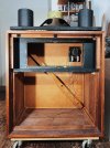
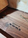

The wood was incredibly dried up, so I oiled both cabinet insides and the woofer boards. Totally not necessary, but I felt sorry for the wooden surface. This also probably fixated some of the tiniest remaining glass fibers.
Then I put some rubber tape around the woofer boards for a better seal with the rest of the chassis.
Next up: cleaning the horns, recapping the crossover, putting rock wool insulation in and reassembly. Everything else (cosmetic) will have to wait a little.
holger7188
Member
Today I tried to clean the very dusty horns. I kind of regret not washing them with soapy water, because they still look kinda dusty. Maybe something for a later day. One of the horns had a sealing rubber tape (which was disintegrated) where it attaches to the chassis. The other one didn’t, so I assume someone either added this or removed it later, not sure how they came fresh from the factory. Anyway, I decided to add new tape:

holger7188
Member
I just wanted to open the L-pad to clean it (which I did), but one thing led to the next and I ended up changing the caps on the crossover, too. It was more trouble than anticipated because of the short leads on the new caps.
They aren’t really fixed properly now (as in: glued to the board) (see photo). Should I fix them in position better?
… and most importantly, now all of a sudden I’m worried about the orientation of the big cap, because I saw there’s a + sign on it that I have no idea what it means? Should I have put it in the other way round?
Certainly not the most elegant job I’ve done.
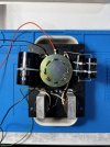
They aren’t really fixed properly now (as in: glued to the board) (see photo). Should I fix them in position better?
… and most importantly, now all of a sudden I’m worried about the orientation of the big cap, because I saw there’s a + sign on it that I have no idea what it means? Should I have put it in the other way round?
Certainly not the most elegant job I’ve done.
Don't worry about the position of the cap. Speaker crossovers are not DC, in terms of polarity.… and most importantly, now all of a sudden I’m worried about the orientation of the big cap, because I saw there’s a + sign on it that I have no idea what it means? Should I have put it in the other way round?
What I sometimes do in these situations, is add lead to components. This gives you more room to arrange the caps. You can put Teflon insulation over the soldered connection, to protect from shorts.


holger7188
Member
I know it is/should be a bipolar cap, that’s why the plus was confusing me. Maybe an indication of the direction of how the cap is wound, I know some caps have that.Don't worry about the position of the cap. Speaker crossovers are not DC, in terms of polarity.
That’s smart, but I don’t really have any wire lying around that would be a good lead extension. What are the leads made of, anyway? Sure doesn’t look like copper.What I sometimes do in these situations, is add lead to components.