


You are using an out of date browser. It may not display this or other websites correctly.
You should upgrade or use an alternative browser.
You should upgrade or use an alternative browser.
Amplifier Circuit Simulation Services
- Thread starter Yamaha5000
- Start date
-
- Tags
- lt spice simulation
Register to hide this ad
Hi
Why do you need or want someone to simulate that design?
From what you posted, I am not sure what you used to draw the schematic but it’s incomplete to start with.
I’ve done a number of amplifier simulations using LTSpice. Imo it’s the most popular free analog simulator out there.
You’d probably get more help over on DIYAudio
Why do you need or want someone to simulate that design?
From what you posted, I am not sure what you used to draw the schematic but it’s incomplete to start with.
I’ve done a number of amplifier simulations using LTSpice. Imo it’s the most popular free analog simulator out there.
You’d probably get more help over on DIYAudio
Yamaha5000
Never settle for 2nd best
Yes I know it is not complete. The complete work is in progress. I know LT Spice and that would be great, just need to hire someone to take this PCB into simulation. This is theHi
Why do you need or want someone to simulate that design?
From what you posted, I am not sure what you used to draw the schematic but it’s incomplete to start with.
I’ve done a number of amplifier simulations using LTSpice. Imo it’s the most popular free analog simulator out there.
You’d probably get more help over on DIYAudio
original schematic:
i

Yamaha5000
Never settle for 2nd best
Plus there are some circuit modifications/additions that I would like to introduce to the circuit and see what changes take place.Hi
Why do you need or want someone to simulate that design?
From what you posted, I am not sure what you used to draw the schematic but it’s incomplete to start with.
I’ve done a number of amplifier simulations using LTSpice. Imo it’s the most popular free analog simulator out there.
You’d probably get more help over on DIYAudio
If you know LTSpice then most of the work is entering the schematic. Once done, I can show you how to simulate it. It's fairly straight forward.
You'll have to substitute devices with models that are equivalent.
Bob Cordell's book on Designing Audio Power Amplifiers, is a good reference that has two chapters on ltspice and modeling
that and the models that he has on his web site.
You'll have to substitute devices with models that are equivalent.
Bob Cordell's book on Designing Audio Power Amplifiers, is a good reference that has two chapters on ltspice and modeling
that and the models that he has on his web site.
Yamaha5000
Never settle for 2nd best
I know of it have never worked with it.If you know LTSpice then most of the work is entering the schematic. Once done, I can show you how to simulate it. It's fairly straight forward.
You'll have to substitute devices with models that are equivalent.
I think he is drafting that schematic in KICAD for the purpose of creating new PCB's
I don't think you can import a KICAD schematic into LTSpice schematic?
I provided him with all substitute part numbers, but I don't think his device symbol will contain that info.
Yamaha5000
Never settle for 2nd best
If you know LTSpice then most of the work is entering the schematic. Once done, I can show you how to simulate it. It's fairly straight forward.
You'll have to substitute devices with models that are equivalent.
Bob Cordell's book on Designing Audio Power Amplifiers, is a good reference that has two chapters on ltspice and modeling
that and the models that he has on his web site.
Attachments
Yamaha5000
Never settle for 2nd best
Please check it out when you get back to the computerWhat’s in the zip file, an LTSpice .asc file ? I can not see it on my iPhone so need my computer.
Does kicad have a built in spice simulator?
First lesson in LTSpice is entering the semi symbols, passive values, connections/nets. Next assign the models......
Yamaha5000
Never settle for 2nd best
As I stated, I didn't know what all the files were and didn't know what would be of use for you!I do not use kicad so it is of no use to me. Why did you not just say they were kicad files as I had asked?
I am not very fond of guessing games, so I am done with this thread. Good luck
Unsure of the road rage reaction!

Last edited:

@Yamaha5000 ... If you are still looking for this, I put together an LTSpice simulation for the CA-1000 power amplifier which seems to behave well using models for modern transistor replacements.
Is there something in particular that you would like to see from the simulation?
Is there something in particular that you would like to see from the simulation?
Attachments
Yamaha5000
Never settle for 2nd best
That is exactly what I have been looking for!@Yamaha5000 ... If you are still looking for this, I put together an LTSpice simulation for the CA-1000 power amplifier which seems to behave well using models for modern transistor replacements.
Is there something in particular that you would like to see from the simulation?
I would like to incorporate some circuit additions that are found in the CA-2010.
For instance: https://en.wikipedia.org/wiki/Wilson_current_mirror
and: Darlington Voltage amplification stage
Last edited:
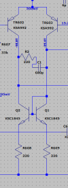
Yamaha5000
Never settle for 2nd best
No Sir, I have notunless you've already designed the modification
Yamaha5000
Never settle for 2nd best
Is this something you would do for me?Adding a current mirror to the input differential amplifier shouldn't be a problem. Modifying the VAS will require a little more thought unless you've already designed the modification.
View attachment 3294158
Adding the current mirror to the input differential amplifier was straightforward as indicated in my previous post. Although the component values may still need to be tweaked somewhat, a quick look at the harmonic distortion in class AB mode showed only a small improvement.Is this something you would do for me?
As for the VAS, a more involved redesign will likely be necessary. I'll have to think about that one and get back to you.
Yamaha5000
Never settle for 2nd best
Thoughts provided from Douglas Self:
Output power is mostly defined by the power rails to provide the voltage drive and the number of output devices to provide enough current carrying capacity and heat dissipation to cope with the load. If you took the 2010 design and use the lower power transformer from the smaller units + reduced the number of OP devices, it is fairly likely there would be enough tolerance variance capability in the design to cope. Lowering the number of OP devices does change the loop characteristics a bit, as the driver stage see a higher impedance and a lower capacitance. If it was a problem increasing the base drive resistors would probably help to compensate but you would likely need to test on a prototype.
Output power is mostly defined by the power rails to provide the voltage drive and the number of output devices to provide enough current carrying capacity and heat dissipation to cope with the load. If you took the 2010 design and use the lower power transformer from the smaller units + reduced the number of OP devices, it is fairly likely there would be enough tolerance variance capability in the design to cope. Lowering the number of OP devices does change the loop characteristics a bit, as the driver stage see a higher impedance and a lower capacitance. If it was a problem increasing the base drive resistors would probably help to compensate but you would likely need to test on a prototype.
So take a CA-2010, remove 1 pair of outputs and use a smaller transformer gets you close to a CA-1000 (which you have), so migrate some of the CA-2010 circuit features to the CA-1000... I'm sure you appreciate the hours of work by @LesE to load the circuit into LTspice, he has also done the class A/AB switching in a neat way, good work.
Did you try the low noise regulated power supply based on that diyaudio thread I sent. The CA-1000 only needs about 100mA which is fine for that voltage regulator.
Did you try the low noise regulated power supply based on that diyaudio thread I sent. The CA-1000 only needs about 100mA which is fine for that voltage regulator.
Yamaha5000
Never settle for 2nd best
No Sir, I like the idea. I did propose the idea to a couple Audio Engineers and didn't get much reaction from them. But that doesn't mean much.Did you try the low noise regulated power supply based on that diyaudio thread I sent. The CA-1000 only needs about 100mA which is fine for that voltage regulator.
Similar threads
- Replies
- 2
- Views
- 96

