
Yamaha5000
Never settle for 2nd best
Precisely the goalso migrate some of the CA-2010 circuit features to the CA-1000


Precisely the goalso migrate some of the CA-2010 circuit features to the CA-1000
I most certainly understand the tremendous effort that @LesE has put forward and the praise is off the chart!I'm sure you appreciate the hours of work by @LesE to load the circuit into LTspice, he has also done the class A/AB switching in a neat way, good work.

I have spoken to the Chief Engineer at Toroid and he feels comfortable that he can design and manufacture a Toroidal Transformer for this application. He needs the V&I load values that the transformer needs to provide.use a smaller transformer gets you close
I'm tempted to "pimp" the CA-1000 on the bench (refurbing) by adding the low noise regulator, do it on a breadboard for "proof of concept" probably add a switch so can switch between OEM and breadboard, maybe a couple of hours work with design, assembly,installation..No Sir, I like the idea. I did propose the idea to a couple Audio Engineers and didn't get much reaction from them. But that doesn't mean much.
Please send that link again.low noise regulated power supply based on that diyaudio thread I sent

What changes did you find in performance with using different current model parts? How did you settle on selecting the ones' you used?@Yamaha5000 ... If you are still looking for this, I put together an LTSpice simulation for the CA-1000 power amplifier which seems to behave well using models for modern transistor replacements.
Is there something in particular that you would like to see from the simulation?
The more I look at your drawing I am more and more impressed, so much great information with the listed V&I values!@Yamaha5000 ... If you are still looking for this, I put together an LTSpice simulation for the CA-1000 power amplifier which seems to behave well using models for modern transistor replacements.
Is there something in particular that you would like to see from the simulation?


For Class A/B operation at rated power, the original design gives a THD of 0.022696%. Adding a current mirror to the input differential amp reduces the THD slightly to 0.011277%. A initial reconfiguration of the voltage amplifier to a Darlington configuration dropped the THD to 0.003198%. That's almost an order of magnitude.What changes did you find in performance with using different current model parts? How did you settle on selecting the ones' you used?
Yes, that's primarily why I simulate these circuits. It can be a very powerful troubleshooting tool.Having the V&I values along with these results could be considered the ultimate troubleshooting tool?
@LesE Have you created any of the other boards in the CA-1000?
Have you created Gerber files from your design?

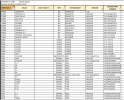
If you provide a list of the replacement parts used, I can plug them into the simulation to see what it looks like.My current parts selections, maybe these should be reevaluated:
See post 30If you provide a list of the replacement parts used, I can plug them into the simulation to see what it looks like.
Beyond amazing!I have transplanted the bias circuit from the CA-1010 into the CA-1000 design but more work is required. I'm not seeing any additional improvement at this point but I may have to simulate the CA-1010 in order to fine tune the modified circuit in the CA-1000.
If you could make a list referencing the TR#'s on the schematic and the replacements used, that would make it a lot easier than trying to figure it out from the photo's.See post 30
If you could make a list referencing the TR#'s on the schematic and the replacements used, that would make it a lot easier than trying to figure it out from the photo's.

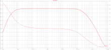
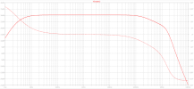
At what location?response using KSC2960 which is better behaved.

