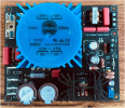
Yamaha5000
Never settle for 2nd best
Not KSA1013Y?KSA1015


Not KSA1013Y?KSA1015
Would you be so kind to take your drawing and highlight the signal path in yellow?When used in the protection circuit, the KSC1845/KSA992 will begin turning on when the load is roughly 2.1 to 2.5 ohms depending on the signal level and frequency. As mentioned in a previous post, it's usually good practice to use complementary pairs here and so if you use the KSC1815/KSA1015, the protection circuit begins to turn on somewhere around 1.5 to 2.0 ohms. So, either should work fine and in both cases, they should have no effect for loads above say 2.5 to 3 ohms.




Complementary PairsNot KSA1013Y?
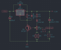
This is roughly the signal path. The red line is the feedback path.Would you be so kind to take your drawing and highlight the signal path in yellow?

Thank you! It looks like I should probe with the QA at each TR Base and Emitter to help define where this loss of signal and high distortion is introduced into the circuit? Any additional thoughts?
First, are you inserting your test signal at AUX or Main In? What is your test signal level? Looking at the spectrum at points within the circuit is not all that helpful. Instead, look at the realtime analog waveform in oscilloscope mode. Also, use your DVM to check some of the DC voltages and compare them to the ones noted on the schematic that I provided earlier.Thank you! It looks like I should probe with the QA at each TR Base and Emitter to help define where this loss of signal and high distortion is introduced into the circuit? Any additional thoughts?
Are you familiar with:First, are you inserting your test signal at AUX or Main In? What is your test signal level? Looking at the spectrum at points within the circuit is not all that helpful. Instead, look at the realtime analog waveform in oscilloscope mode. Also, use your DVM to check some of the DC voltages and compare them to the ones noted on the schematic that I provided earlier.
No, I'm not familiar with either.Are you familiar with:
QuantAsylum?
Vintage Audio Review?
Did you try the low noise regulated power supply based on that diyaudio thread I sent. The CA-1000 only needs about 100mA which is fine for that voltage regulator.
Have you prepared an integrated schematic?I'm tempted to "pimp" the CA-1000 on the bench (refurbing) by adding the low noise regulator, do it on a breadboard for "proof of concept" probably add a switch so can switch between OEM and breadboard, maybe a couple of hours work with design, assembly,installation..

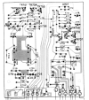
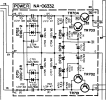
No need to apologize. I should mention that I have changed the drivers from TTC/TTA004 to the MJE15032/33 which preliminarily looks good in simulation. The average power dissipation should be somewhere around 800-900mW which is within the operating limits for the TTC/TTA but a heatsink will likely be required. The MJE devices should be bulletproof in this application. Another possible candidate is the KSC2703 and KSA940. I'll let you know if I see any potential problems with the MJE's.@LesE I must take a moment and extend an apology to you for sending that WTF parts list. After further review I can see that I really screwed that up!
Yesterday I went back to both Main Boards and changed all the transistors out to what you provided with the drawing. Now I am anxious this morning to run test on these boards to see what changes are found.
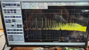
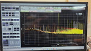
I am connected to AUX. I am sure I don't have something configured correctly in the QA Automated Test.The amplifier should provide just over 30dB of gain and I see on your display that the measured gain is around 46dB so I'll assume that you are applying the test signal to the AUX port. Is this the case and if so, what is your test signal level?

 drive.google.com

This post #70and 71hen you may need to look at the regulated power supply as a possible source