


You are using an out of date browser. It may not display this or other websites correctly.
You should upgrade or use an alternative browser.
You should upgrade or use an alternative browser.
Amplifier Circuit Simulation Services
- Thread starter Yamaha5000
- Start date
-
- Tags
- lt spice simulation

Yamaha5000
Never settle for 2nd best
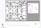
Screenshot of the schematic?

Here is the circuit schematic for the unmodified CA-1000 as well as two modifications and a modified CA-1010.
Attachments
Yamaha5000
Never settle for 2nd best
I also have to wonder about what negative effects are being seen from C601 since it is an Bipolar electrolytic.
Yamaha5000
Never settle for 2nd best
Are these complete?Here is the circuit schematic for the unmodified CA-1000 as well as two modifications and a modified CA-1010.
Well, it looks like I'm going to have to throw in the towel. The modified designs were showing bad overshoot on the rising edge of a square wave. Addressing that problem reduced the amplifier slew rate. In addition, overall noise was worse as compared to the original amplifier design. While the THD was improved at lower frequencies, other parameters were degraded. As a result, I'm going to suggest that you stay with the original design.Are these complete?
Yamaha5000
Never settle for 2nd best
This is caused by the Current Mirror or VAS or both?Well, it looks like I'm going to have to throw in the towel. The modified designs were showing bad overshoot on the rising edge of a square wave. Addressing that problem reduced the amplifier slew rate. In addition, overall noise was worse as compared to the original amplifier design. While the THD was improved at lower frequencies, other parameters were degraded. As a result, I'm going to suggest that you stay with the original design.
I'm not entirely sure but adapting the -1010 design to the -1000 required increasing it's input impedance as well as the overall amplifier gain which is likely the cause of the increased noise.This is caused by the Current Mirror or VAS or both?
Yamaha5000
Never settle for 2nd best
What changes did you make to the 1010 and what was the results?I'm not entirely sure but adapting the -1010 design to the -1000 required increasing it's input impedance as well as the overall amplifier gain which is likely the cause of the increased noise.
The changes can be seen in the schematic posted previously.What changes did you make to the 1010 and what was the results?
Yamaha5000
Never settle for 2nd best
Results?The changes can be seen in the schematic posted previously.
I'll post later if I have some time.Results?
Yamaha5000
Never settle for 2nd best
Can you send me the LTspice files for all the different designs?I'll post later if I have some time.
Yamaha5000
Never settle for 2nd best
Thank you for putting in all the effort to try to assist, I do appreciate it greatly!I'll post later if I have some time.

Here are all of the results and LTSpice files. I made a few more adjustments on options A and B that seem to work better but I did drop the option of modifying the -1010 design since there were too many problems. Slew rate is still a little slower but the noise is fine. The THD summary shows results prior to adjustments but should be fairly close.
 drive.google.com
Yamaha CA-1000 Redesign - Google Drive
drive.google.com
Last edited:
Yamaha5000
Never settle for 2nd best
So you are saying the CA-1000 does benefit from the changes and the CA-1010 doesn't?Here are all of the results and LTSpice files. I made a few more adjustments on options A and B that seem to work better but I did drop the option of modifying the -1010 design since there were too many problems. Slew rate is still a little slower but the noise is fine. The THD summary shows results prior to adjustments but should be fairly close.
Google Drive: Sign-in
Access Google Drive with a Google account (for personal use) or Google Workspace account (for business use).drive.google.com
No I'm not saying that. Modifying the -1010 amplifier to replace the -1000 amplifier involves changing it's input impedance and the overall gain which are both lower in the -1010. You have to be careful adjusting the feedback loop to increase gain since it can lead to instability which is what I was observing. I'm sure that this can be overcome but that will require more time which I don't have right now. Besides, it looks like you have two other potential options to pursue if you chose to do so.So you are saying the CA-1000 does benefit from the changes and the CA-1010 doesn't?
Yamaha5000
Never settle for 2nd best
I do have the immediate need to produce the new 1000 Main Amp boards. I will look at option A and B and decide with others (@MZB) input which direction to proceed. Then I can send this to the guy doing the KIKAD work to get these into production.No I'm not saying that. Modifying the -1010 amplifier to replace the -1000 amplifier involves changing it's input impedance and the overall gain which are both lower in the -1010. You have to be careful adjusting the feedback loop to increase gain since it can lead to instability which is what I was observing. I'm sure that this can be overcome but that will require more time which I don't have right now. Besides, it looks like you have two other potential options to pursue if you chose to do so.
As you have seen from the 1000 that I have on the bench my measurements are far worse than what you have simulated. I assume this has some degree of difference due to real world conditions. When you have the time please look at the other possible alternatives.
I know you are very busy, but when you have the opportunity please take a look at the Power Supply.
Yamaha5000
Never settle for 2nd best
Similar threads
- Replies
- 2
- Views
- 90

