Yamaha5000
Never settle for 2nd best
In what location? Revised schematic?In this case, I used a KSC1845 and KSC3503 for the VAS.


In what location? Revised schematic?In this case, I used a KSC1845 and KSC3503 for the VAS.
Please don't use the parts that I selected, I much prefer you to tell me what you have located that provides the best performance.With your choices

Voltage amplifier TR604 and TR605.At what location?
Voltage amplifier TR604 and TR605. Design is currently a work in progress.In what location? Revised schematic?
I wasn't planning to. Just responding to your mention of reevaluation.Please don't use the parts that I selected,
My current parts selections, maybe these should be reevaluated:
Any progress?Voltage amplifier TR604 and TR605. Design is currently a work in progress.
The process takes time. Probably a few more days.Any progress?
Are you saying that the CA-1010 in the simulation doesn't meet these specs:The process takes time. Probably a few more days.
I ended up simulating the CA-1010 for use as a benchmark and I'm beginning to think it would be best to stick with the original bias configuration since the CA-1010 uses transistors to switch the class of operation which appears to be triggered by a change in the regulated voltage. I think that focusing on the input and voltage amplifier stages will raise THD performance to a level that is nearly equal to the CA-1010.
I haven't seen any indication in the service manual of how much the unregulated power supply voltages will droop at full power so I haven't factored that in at this point but I'll probably apply a ballpark estimate of 10% for class AB operation in the final assessment.
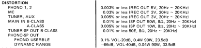

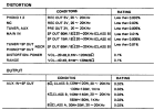
I am certainly no fan of additional hard switches and associated wiring. I have gone to great lengths to eliminate as many and as much as I see possible to rid the unit of these items. My primary focus to date has been with S/N and Crosstalk issues.Sorry if I was unclear. My reference was with respect to the CA-1000 since it is the subject of this exercise. The only parameter that I looked at so far for the SA-1010 is the THD in class B mode at 1 KHz for rated power and it did perform better than the 50W spec that you posted. But that's before factoring in some power supply sag. At 50W output, I expect that the -1010 should easily exceed specs.
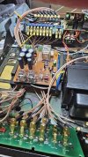
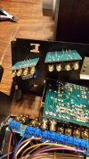
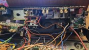


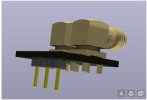

Very good. Thanks for getting that measurement.@LesE Class A voltages @B+/B- 20.12vdc
No, only what you see on the schematic posted earlier.@LesE Did you run a simulation with these parts:
MJ15004G paired with 2SA566 ?
MJ15004G paired with MJE15033G ?
MJ15003G paired with 2SC680 ?
MJ15003G paired with MJE15032G?
View attachment 3298550
Is it correct for me to assume you created the circuit with the original parts? and then changed them to your preference?No, only what you see on the schematic posted earlier.
No, unfortunately models for the original devices do not exist as far as I know.Is it correct for me to assume you created the circuit with the original parts? and then changed them to your preference?


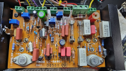
When used in the protection circuit, the KSC1845/KSA992 will begin turning on when the load is roughly 2.1 to 2.5 ohms depending on the signal level and frequency. As mentioned in a previous post, it's usually good practice to use complementary pairs here and so if you use the KSC1815/KSA1015, the protection circuit begins to turn on somewhere around 1.5 to 2.0 ohms. So, either should work fine and in both cases, they should have no effect for loads above say 2.5 to 3 ohms.@LesE
I went back and took a more serious look at the drawing you provided and find a couple items in question:
TR606 is a 2SC458C you show a replacement with a KSC1845, all my research has shown that this should be a KSC1815
TR608 is a 2SA561 you show a replacement with a KSA992, all my research has shown that this should be a KSA1013Y
After some further review I am also finding this statement in the Yamaha Service Manual:
My concern here is that I am using 4 ohm dummy loads
View attachment 3298831