• Please note that Audiokarma will be offline briefly for updates early on Monday morning, September 28th.

Another A-700 repair thread

Ok, so help us understand where you are a little better.

Did you get the bias to adjust properly? What is the DC offset of the amp right now?

Did you find any components that look burnt, corroded or otherwise faulty?

It sounds like you are testing the amp. When you turn it on, after a few seconds the relay clicks. But then after a minute or so the relay clicks again? This amp doesn't have a protection light, but what you are describing sounds like the speaker protection circuit is activating and opening the relay.

If this is what you are describing, then there is a fault in the amp.

Please let us know if you can get the bias adjusted properly. This is probably not the issue, but since it was reported being so high you should do this first.

Next, you really need to desolder the caps and any other components in the glue damage field. These components need to be tested.

After that, if these things don't expose any issues then you will need to do more measurements At that point I will not be your best guide. But, the collective wisdom is find the fault and repair it before doing any thing else like recapping.
 
Leave the speakers connected, but make sure both speaker select switches are off. Then see if it pops.

Between the output of the amp section and the speaker terminals are 1) the protection relay and 2) the speaker select switches. If the relay AND switches are off, the only way for a signal to reach the speakers is through the ground path. That's what we are checking.
I tested your suggestion, I did not get any pop
 
Ok, so help us understand where you are a little better.

Did you get the bias to adjust properly? What is the DC offset of the amp right now?

Did you find any components that look burnt, corroded or otherwise faulty?

It sounds like you are testing the amp. When you turn it on, after a few seconds the relay clicks. But then after a minute or so the relay clicks again? This amp doesn't have a protection light, but what you are describing sounds like the speaker protection circuit is activating and opening the relay.

If this is what you are describing, then there is a fault in the amp.

Please let us know if you can get the bias adjusted properly. This is probably not the issue, but since it was reported being so high you should do this first.

Next, you really need to desolder the caps and any other components in the glue damage field. These components need to be tested.

After that, if these things don't expose any issues then you will need to do more measurements At that point I will not be your best guide. But, the collective wisdom is find the fault and repair it before doing any thing else like recapping.


I tried to adjust the bias, but it is fluctuating too much to get a clear measurement. I tried to lower it as much as possible, but its still going from 0mV to something like 80mV all the time.
In my opinion there are no corroded or faulty looking components, but I will desolder the caps where I removed the glue and check their capacity
 
Is the "Class A" switch off when you see this bias fluctuation?
The problem could be a bad solder joint (it is common for these amps to have many cracked solder joints), or possibly damaged / broken legs on the 2SD400 bias compensation transistors (small devices mounted to top of heatsinks) which is another common problem. If you like the amp, the first thread you linked by "Scottfer55" is a great one to follow along for a full rebuild, mine is much older and not good. Everything for a successful long-term rebuild is explained in Scottfer's thread.

Before you do anything on the amp, I strongly recommend building a DBT (dim bulb tester), then use it for all further testing until the issue is resolved.
If bias is jumping from 0mV to 80mV I would not deem it safe to leave running on full mains power.
 
If bias is jumping from 0mV to 80mV I would not deem it safe to leave running on full mains power.
Zaibatsu, thanks for the great suggestions and your experience with this amp.

Just curious, @guac, is the 0 to 80 mv fluctuations DC offset (measured at the speaker terminals) or bias (measured internally)?
 
Its measured at the terminals, I couldn't reach the contacts on the resistors while having it plugged in.

Additionally I got around removing the caps for glue removal and at the same time I checked the caps. C211,C212, C183-C186, C205 and C210 all are broken. Or the multimeter doesn't register any capacitance.

@zaibatsu thank you very much for your input. I checked the solder joints on the lower backside of the main pcb and they seemed fine so far. Maybe I will have another look at the joints. Any idea how to check the compensation transistor for correct function?
 
You're measuring DC offset at the speaker terminals. Not bias. Should be as close to zero as possible, and shouldn't fluctuate much unless you have music playing. In which case it will bounce around, there being a signal present.
 
Its measured at the terminals, I couldn't reach the contacts on the resistors while having it plugged in.

Additionally I got around removing the caps for glue removal and at the same time I checked the caps. C211,C212, C183-C186, C205 and C210 all are broken. Or the multimeter doesn't register any capacitance.

@zaibatsu thank you very much for your input. I checked the solder joints on the lower backside of the main pcb and they seemed fine so far. Maybe I will have another look at the joints. Any idea how to check the compensation transistor for correct function?
As bberkom has said, that is the DC offset at the terminals. You need to follow the service manual exactly as it says and measure bias. Still, if the DC offset is being measured with the amp on but with the volume at 0 and it is bouncing around that is not good.

Good that you have the caps out to clean. Make sure you take pictures so you can install the right ones in the right place with the polarity correct. I doubt all the caps are bad enough that none of them measure any capacitance. You need to make sure you are using your meter correctly or that it is working correctly. You can't go on if you can't make these measurements. Do you have any caps that are new that you could test with your meter?
 
If you are going to be successful with this remote diagnostics and repair, which we all want you to be, I suggest you take a step back for a moment. You need to be able to read the service manual and instructions that people will give you precisely. You will also need to report back to the thread accurate information. It will be difficult for anyone trying to help you remotely with out these things. Plus you need to think critically about what you are doing. There is a reason DC offset and Bias have different names, because they are different things and differences like that make a big difference. I tell you these things because I have learned these lessons the hard way, and just want to help you along.
 
I doubt all the caps are bad enough that none of them measure any capacitance
I completely agree, I usually find one or fewer dead caps in a receiver or amp. If there are more, there are usually burnt resistors and transistors, too. Because this one was working, you can rest assured that having 8 completely dead, completely open caps is pretty unlikely.

Does your meter have a cap test function? What meter do you have? Can you post a pic?
 
Last edited:
Thank you all, I appreciate your help. I try to give my answers as clear as possible.

So what I did in the meantime:
  • I checked the compensation transistors and they are fine, I took them out of the circuit and measured according to some guides online. Everything checked out.
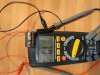
  • PXL_20210516_102031142.jpg this is my meter (RND 355). I does have a cap function. But when I check the caps I get OL for all of them. And I don't have any other caps lying around the check. I got it a few weeks ago. Is it possible that a new battery would result in different measurements? I ordered one of those component testers from china, but it will take some time until it arrives
  • Next week I will see where I can get the parts for a DBT, what kind of bulbs should I get? How does it work with LED Bulbs, does a 100W equivalent 12W LED bulb work? In the service manual it says 360W, how would I get this wattage with bulbs?
  • I will wait to check the idle voltage again until I have a DBT ready.
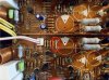
  • Screenshot 2021-05-16 123922.jpg I replaced one corroded bridge wire besides one of the capacitors
 
So, I recently bought a Yamaha A-700 amp,
I would appreciate any tips and tricks regarding the popping issue I experience.

Thank you all very much

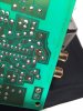
I had had multiple Yamahas that developed popping noises. One had an open resistor due to glue/corrosion.
One required re-flowing solder joints on the main board.
A third required re-flowing solder on an RCA jack connector. A preamp was fixed with Deoxit on a selector switch.
Yamaha M-45 OpenResistor.jpg
Yamaha Phono Input.JPG
image.png
 
Thank you all, I appreciate your help. I try to give my answers as clear as possible.

So what I did in the meantime:
  • I checked the compensation transistors and they are fine, I took them out of the circuit and measured according to some guides online. Everything checked out.
  • View attachment 2228255 this is my meter (RND 355). I does have a cap function. But when I check the caps I get OL for all of them. And I don't have any other caps lying around the check. I got it a few weeks ago. Is it possible that a new battery would result in different measurements? I ordered one of those component testers from china, but it will take some time until it arrives
  • Next week I will see where I can get the parts for a DBT, what kind of bulbs should I get? How does it work with LED Bulbs, does a 100W equivalent 12W LED bulb work? In the service manual it says 360W, how would I get this wattage with bulbs?
  • I will wait to check the idle voltage again until I have a DBT ready.
  • View attachment 2228260 I replaced one corroded bridge wire besides one of the capacitors
Fantastic!
  • There is a great thread here on testing transistors: https://audiokarma.org/forums/index.php?threads/bipolar-junction-transistor-testing-basics.43186/
  • I will see if I can find the instructions on that meter. I use one of those Chinese component testers. While they don't test everything, they are quite handy.
  • You cannot use an LED in a DBT. The LED does not behave like a incandescent filament. The incandescent filament increases resistance as it heats up, reducing current flow. That's why a DBT offers some protection. A bulb of 100 - 150W is probably good for this amp
  • Make sure to look at the green resistors that are standing on edge. Those are the "fusable" resistors. Look for signs of burning or darker colors on them.
 
Thank you all, I appreciate your help. I try to give my answers as clear as possible.

  • View attachment 2228255 this is my meter (RND 355). I does have a cap function. But when I check the caps I get OL for all of them. And I don't have any other caps lying around the check. I got it a few weeks ago. Is it possible that a new battery would result in different measurements? I ordered one of those component testers from china, but it will take some time until it arrives

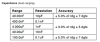
Is it possible that the caps are out of you meters range? From the manual:
upload_2021-5-16_9-43-37.png
Maybe see if you can find a cap that is <100µF
 
I do believe the 1000uF cap is not in the meter's range. Can you test one under 100uF?

Also, that is not an original cap. That's a Nichicon UKZ, I believe. It's a very fine cap and unlikely to simply go open unless there was other damage. Are all the caps black with gold lettering (or vice versa)? Perhaps a previous owner recapped the unit.
 
I do believe the 1000uF cap is not in the meter's range. Can you test one under 100uF?

Also, that is not an original cap. That's a Nichicon UKZ, I believe. It's a very fine cap and unlikely to simply go open unless there was other damage. Are all the caps black with gold lettering (or vice versa)? Perhaps a previous owner recapped the unit.
That cap looks like it has the dreaded glue on it. Hopefully someone didn't recap and not remove the glue.
 
That cap looks like it has the dreaded glue on it. Hopefully someone didn't recap and not remove the glue.
I stand corrected. I looked into my stock unit and the caps are UKZ - black with gold lettering. The more I learn about this series of amps, the more I think they are really under-appreciated.
 
I stand corrected. I looked into my stock unit and the caps are UKZ - black with gold lettering. The more I learn about this series of amps, the more I think they are really under-appreciated.
Agreed. I just picked up an A-1000. Can't wait to look into it. Couple projects before that though.
 
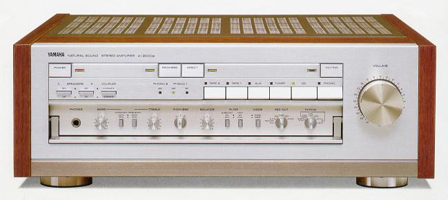
You need to get and A-2000..:thumbsup:

a-2000a(1).JPG
a-2000a.JPG
 
Back
Top Bottom