

You are using an out of date browser. It may not display this or other websites correctly.
You should upgrade or use an alternative browser.
You should upgrade or use an alternative browser.

Asmodeus2112
Super Member
Nice, I wonder how many were made. Continuing the threadjack, but it would be cool if there we reports of how many of these amps were made like they do for cars. Currently I collect what comes my way locally, but to get into things like an A-2000 it probably requires a different price of admission and a hard target search. I'm sure with your service you get opportunities that most of us won't come across often.Guess who has one ...
Looks to me like something besides glue got spilled in there (sorry I'm so late replying, didn't look at the pics before). The brown splotches are NOT glue, especiallly since they are all over the resistors too. Looks like chocolate milk, eh?
Look for corroded leads on anything inside those splotches -- looks exactly like the board on equipment I've worked on where a capacitor leaked out. The electrolyte is corrosive to copper, and turns the leads green. Those green painted resistors have painted leads, don't confuse that with corrosion.
Get one of those cheap ($25) component testers for checking capacitors and transistors. Not the most accurate things on the face of the planet, but they do the job well enough for testing. Very much handier (and more accurate) that a multimeter, especially for capacitors as you get ESR and leakage results as well as capacitance.
Look for corroded leads on anything inside those splotches -- looks exactly like the board on equipment I've worked on where a capacitor leaked out. The electrolyte is corrosive to copper, and turns the leads green. Those green painted resistors have painted leads, don't confuse that with corrosion.
Get one of those cheap ($25) component testers for checking capacitors and transistors. Not the most accurate things on the face of the planet, but they do the job well enough for testing. Very much handier (and more accurate) that a multimeter, especially for capacitors as you get ESR and leakage results as well as capacitance.

zaibatsu
yam
Enjoy, the A-1000 is a beautiful sounding amp once restored correctly.Agreed. I just picked up an A-1000. Can't wait to look into it. Couple projects before that though.
Not a small task to do right.
The A-2000 is not from the same family thus not necessarily an "upgrade" IMO, it's a much later amplifier (~1986-1987?) based on the B-2x. The A-1000 was the TOTL integrated in its time (1983) and has a parallel in Japan called the A-950 which got the copper chassis treatment.
So technically, the A-950 is the "upgraded" A-1000 - same era, same circuitry.

Semanon
Super Member
I’m quite pleased with my unrestored A700. Will get around to reconditioning it sometime soon, but for now it’s running smoothly as a bedroom system. They are still vastly undervalued, IMO. I’d probably skip the A-1000 as an upgrade and hold out for something like a A-2000. If I sold most of my integrated amps I could afford one. Sometimes I think owning one would be so much simpler...but maybe less fun, too.

guac
New Member
Is it possible that the caps are out of you meters range? From the manual:
View attachment 2228410
Maybe see if you can find a cap that is <100µF
Well what a stupid mistake from my side. I will take them to the office tomorrow and check if we have a better multimeter there. I guess trouble shooting is not my strength...
Where would I get a 150W bulb tho, I can only find LED bulbs, everything else is hard to find here in Switzerland

I found some 120W halogen bulbs, maybe those work aswell?
Yes.
I have been using odd sized halogen bulbs for years, like 105w etc. That 120w should do just fine for the A-700.
Cheers,
James
guac
New Member
today i got the first parts for the DBT, will build that once I have everything
Yesterday I got around checking the caps in the office
Yesterday I got around checking the caps in the office
- the 1000uF/25V caps on the main pcb measured: 750uF and 786uF
- the 680uF/80V caps measured: 574uF and 577uF
- and the 330uF/25V caps measured: 216uF, 231uF, 222uF and 221uF
Asmodeus2112
Super Member
today i got the first parts for the DBT, will build that once I have everything
Yesterday I got around checking the caps in the office
all except the two 680uF caps are out of tolerance (20% i believe), should they be changed?
- the 1000uF/25V caps on the main pcb measured: 750uF and 786uF
- the 680uF/80V caps measured: 574uF and 577uF
- and the 330uF/25V caps measured: 216uF, 231uF, 222uF and 221uF
Well, IMO, unless the component is bad, I would put them back in until you repair the fault. I agree with Semanon, that since they are out, might as well replace them, but that means days waiting for new parts where if you put them back in you can continue to troubleshoot. Your call on how much time you have and how fast you want to work through this. I would ultimately replace these though.
Semanon
Super Member
Great points, Asmodeus. If you change them now, you won’t have the same conditions, making troubleshooting harder. I hate waiting for orders.Well, IMO, unless the component is bad, I would put them back in until you repair the fault. I agree with Semanon, that since they are out, might as well replace them, but that means days waiting for new parts where if you put them back in you can continue to troubleshoot. Your call on how much time you have and how fast you want to work through this. I would ultimately replace these though.
OTOH, the fewer solder cycles the better.
Last edited:
zaibatsu
yam
Just clean all the glue, replace any corroded jumpers (you can use spare resistor leads) and put the old caps back. You can solder them in lightly (just leave the legs straight after insertion, don't fold), those values should be fine for troubleshooting. You can replace the caps later after the problem is fixed.
Make sure you have some mini-grabber leads for your multimeter, they are useful for voltage testing, and for measuring bias/idle current. You only need a 100W bulb for the A-700, even 80W will work fine. Make sure the bulb is wired in series, if you've built it correctly when you power up the amp through it, the bulb will grow bright momentarily then dim.
After this you can re-test DC offset at the speaker terminals (only possible if the relay engages, this connects the amplifier output to the speaker terminals). You can use your normal multimeter leads for this as you probably already did.
The A-700 uses a DC servo so it's unusual to have DC drift issues (and it should always measure very close to 0mV). There's a very small possibility one of the front end FET transistors has gone bad (2SK-117, x4) but I haven't seen it happen on these amps yet. I would get a magnifying glass and check all solder joints under a good light, usually at least some have crack rings on these amps.
Make sure you have some mini-grabber leads for your multimeter, they are useful for voltage testing, and for measuring bias/idle current. You only need a 100W bulb for the A-700, even 80W will work fine. Make sure the bulb is wired in series, if you've built it correctly when you power up the amp through it, the bulb will grow bright momentarily then dim.
After this you can re-test DC offset at the speaker terminals (only possible if the relay engages, this connects the amplifier output to the speaker terminals). You can use your normal multimeter leads for this as you probably already did.
The A-700 uses a DC servo so it's unusual to have DC drift issues (and it should always measure very close to 0mV). There's a very small possibility one of the front end FET transistors has gone bad (2SK-117, x4) but I haven't seen it happen on these amps yet. I would get a magnifying glass and check all solder joints under a good light, usually at least some have crack rings on these amps.
guac
New Member
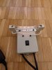
Finally got all the parts for the DBT today. Put it together and works just as advertised.
Redid the Idle adjustment, this time the correct one. Got it to 15-16mV on both sides, pretty happy that it worked.
I also redid the bias check according to the post in the Solid State forum, and measured stable 1.1mV, first I was worried it's too low but according to @zaibatsu it should be just fine.
currently checking the amp with some music, so far no pops or nothing. I really was to eager to just replace the caps instead of going at it in a smart way, I'm sorry about that.
Thank you all very much for your help. Is a recap necessary now? Or is it back in working condition the way it is now?
cheers

With or without the dim bulb ?Redid the Idle adjustment,
Before you plug this puppy into the mains directly you need to adjust the bias back to zero. Otherwise the bias will be way ,way to high. Then once your on the mains readjust the bias per manual.With the dim bulb. Should i do it without? In that case i did not do it fully correct
Asmodeus2112
Super Member
You should not adjust bias on DBT. It will be set too high when you go to mains. On DBT set the bias to the lowest possible adjustment. Go to mains and adjust it up to the proper level.With the dim bulb. Should i do it without? In that case i did not do it fully correct
zaibatsu
yam
Nice work.
Just some terminology correction: what you measure at the white resistors is idle (also called bias), that should be ~15.5mV. What you measure at the speaker terminals is called DC offset (or DC balance), that should be as close to 0mV as possible. Did you check both channels at the speaker terminals? You should get a L and R reading, both near 0mV.
As above, check idle / bias (15.5mV) after removing DBT. Also yes it's probably still good to recap, use the DBT on first power up after recap (and wait for a relay click) to confirm you didn't make errors. There are parts recommendations in Scottfer's thread, make sure you use mouser / digikey and not ebay etc.
Just some terminology correction: what you measure at the white resistors is idle (also called bias), that should be ~15.5mV. What you measure at the speaker terminals is called DC offset (or DC balance), that should be as close to 0mV as possible. Did you check both channels at the speaker terminals? You should get a L and R reading, both near 0mV.
As above, check idle / bias (15.5mV) after removing DBT. Also yes it's probably still good to recap, use the DBT on first power up after recap (and wait for a relay click) to confirm you didn't make errors. There are parts recommendations in Scottfer's thread, make sure you use mouser / digikey and not ebay etc.