• The move to the new server is done. There are some software and database maintenance updates in process. This has us passing the hat around to help out. We appreciate any donations. Seriously, even a dollar helps. The payment page may be found here - https://www.audiokarma.org/support.html

Another Electro Voice Interface D Restoration Thread

MCM_Fan

AK Subscriber
I've read other Electro Voice Interface D restoration threads and they seem to all be unique. I recently picked up a pair of these classic speakers and need some help.

I learned of these through a thread posted in Dollars & Sense. Long story short, they didn't come with the equalizer and the seller was unable to locate one of the original woofers.

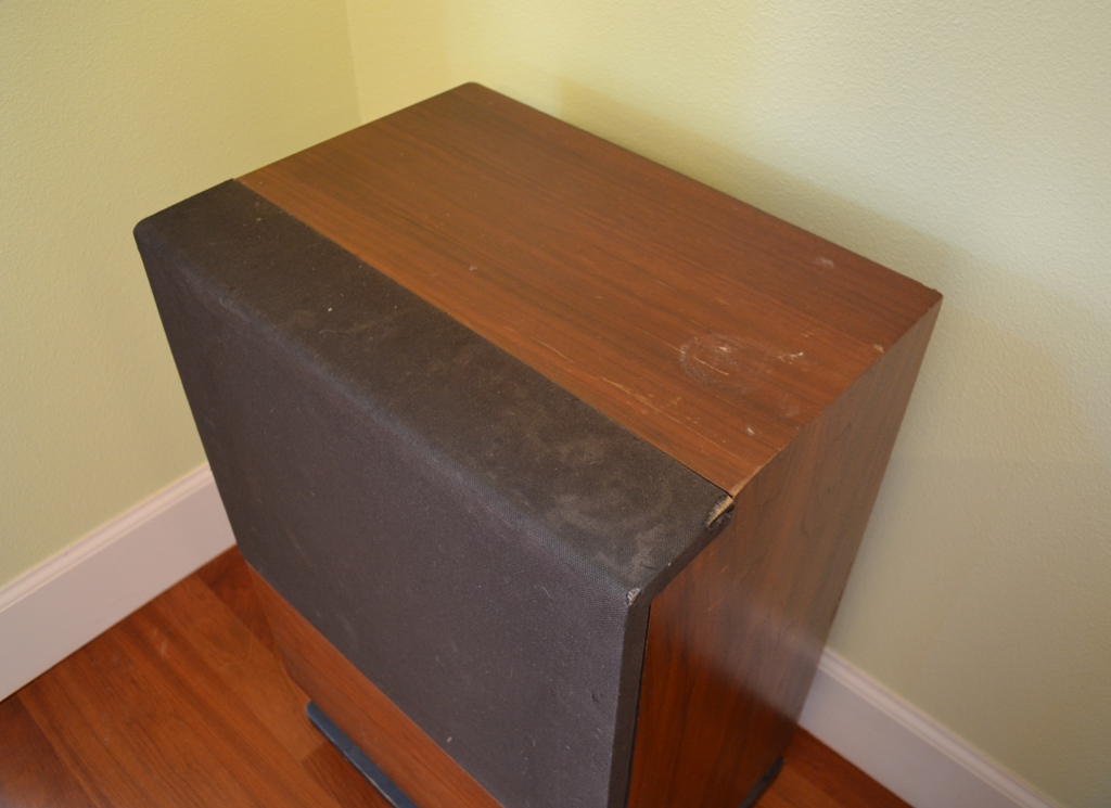
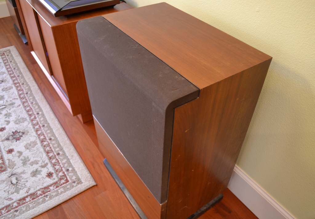
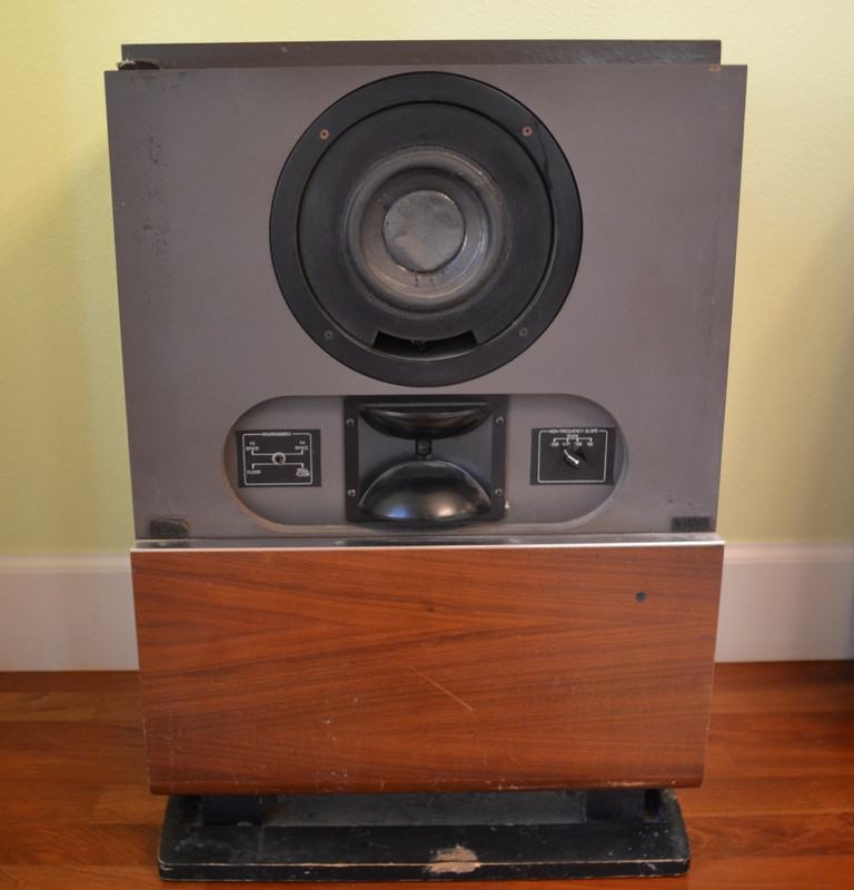
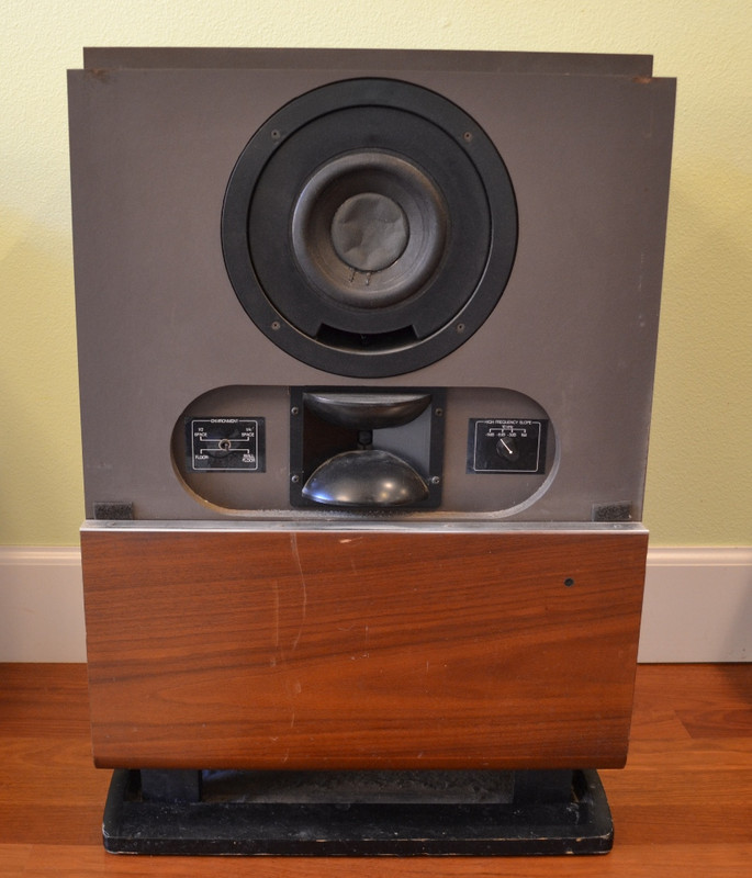
Here's some photos of the speakers in their current state:
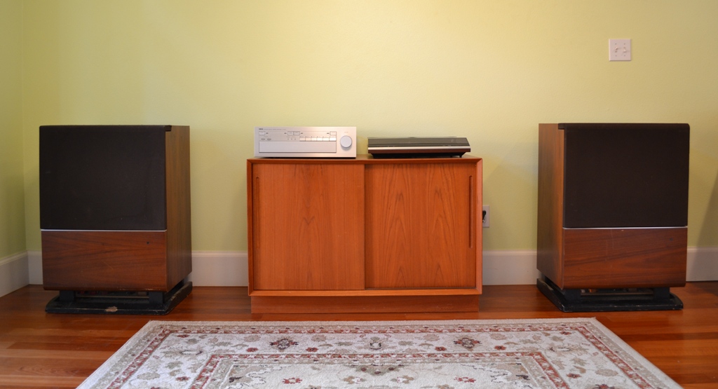
EV-Interface-D-1.jpg


EV-Interface-D-2.jpg


EV-Interface-D-3.jpg


EV-Interface-D-4.jpg


EV-Interface-D-5.jpg


I expect this to be a slow process as I try to locate the missing pieces needed to complete this project. I will post updates whenever I have made any significant progress.
 
Last edited:
Register to hide this ad
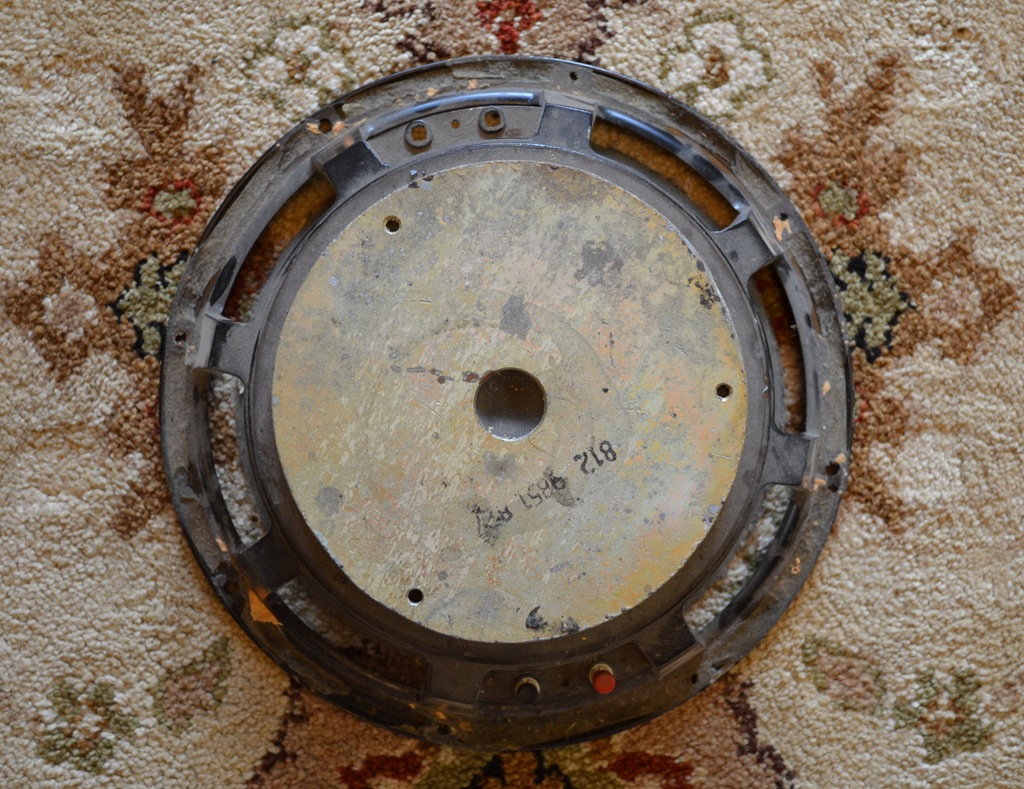
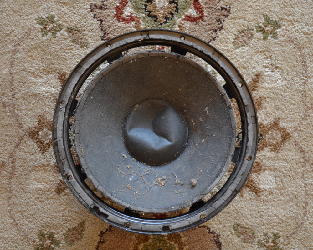
The first issue is the woofers. Here's a couple photos of the one original woofer I received:

EV-Interface-D-6.jpg


EV-Interface-D-7.jpg


It obviously needs some work, but the bigger issue is locating, or fabricating from parts, a second woofer. I have received some advice from GordonW on what I need to look for to construct a compatible woofer from other Electro Voice woofer parts.
 
Last edited:
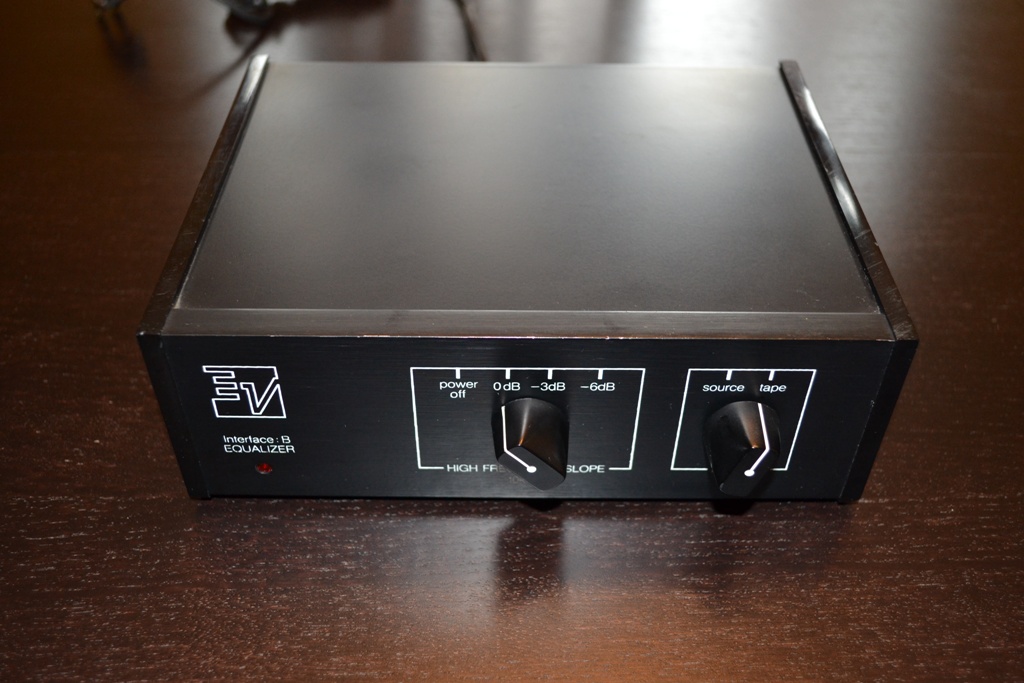
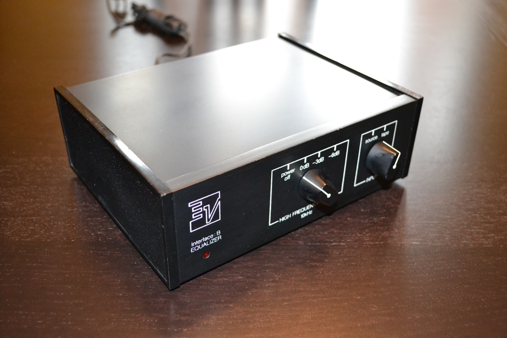
But, the good news is I have sourced an equalizer - sort of. I picked up an EV Interface B Equalizer off eBay. It arrived today. Here's what it looks like:

EV-Interface-B-3.jpg


EV-Interface-B-4.jpg


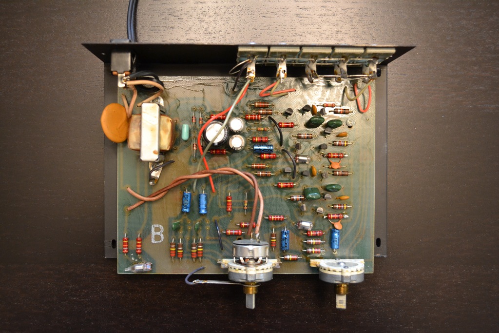
And here's what it looks like with the top off:

EV-Interface-B-5.jpg
 
Last edited:
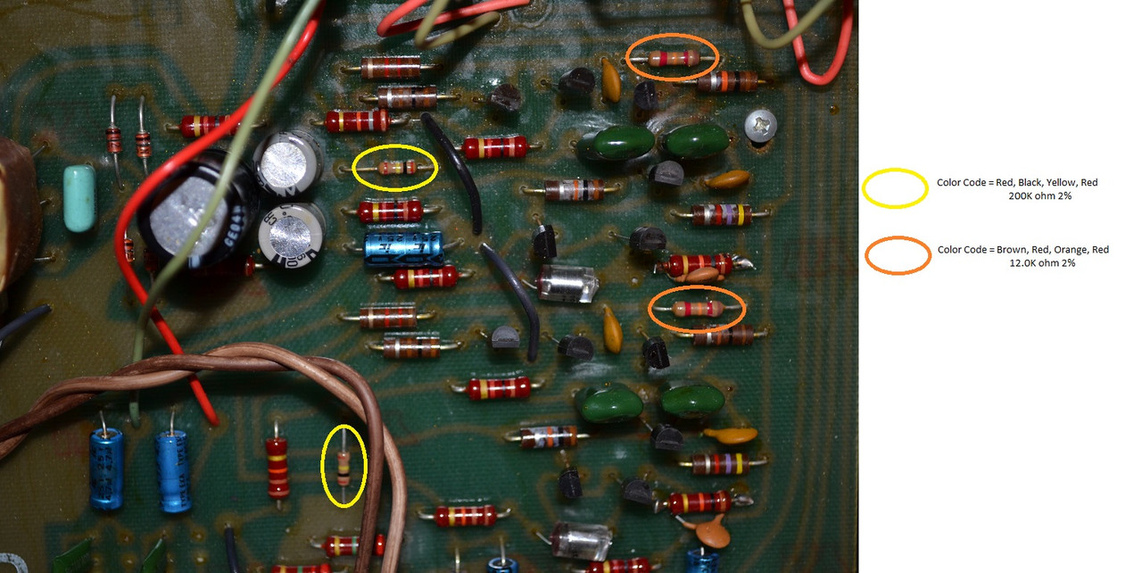
Of course, the reason I picked up the Interface B Equalizer is with the intention to convert it for use with my Interface D speakers. I've read in multiple threads that it's possible to do so by simply changing the values of 4 resistors. Based on this post in this thread, it looks like I just need to change the resistors from 12.0K and 200K to 13.0K and 220K. That should be easy enough. For those attempting a similar conversion, here's a photo of my Interface B PCB that shows the locations and original values for these four resistors:

EV-Interface-B-EQ-1.jpg
 
Last edited:
While comparing my Interface B PCB to the Interface D PCB shown here, I noticed some additional differences. The PCBs are the same, the differences are in the component stuffings.

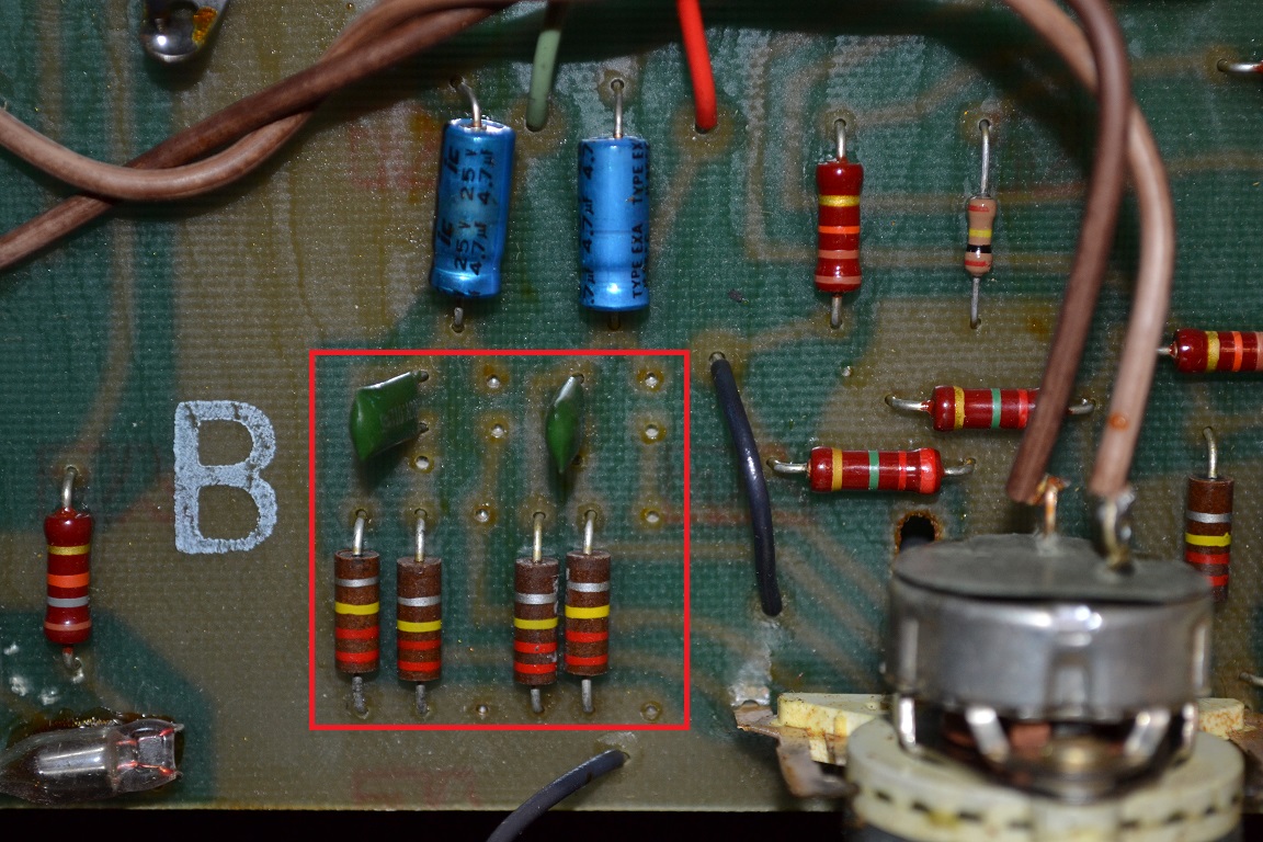
First, on my Interface B PCB, there are some "missing" components in the area enclosed in the red square in this photo:

EV-Interface-B-EQ-2.jpg


If you compare that photo to one of the Interface D PCB, you will see than two of the 220K resistors are missing, as are two of the film caps.

index.php


You can see in the Interface D Equalizer photo, the film caps appear to be two different sizes. These components seem to be in the HF frequency part of the circuit, but I do not have a schematic to verify. Perhaps someone more familiar with the design can let me know if these missing parts are important and need to be installed to make this EQ work correctly with the Interface D speakers. And, if they do need to be populated, if anyone can provide the correct vales for the caps (either from a schematic, or checking their Interface D equalizer).

Thanks in advance for any help.
 
Last edited:
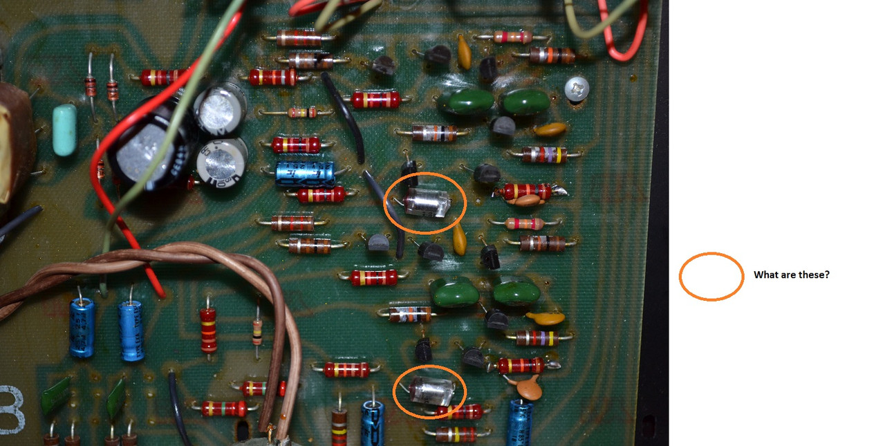
The other difference is the two silver metal devices that are encapsulated in clear plastic as shown in this photo:

EV-Interface-B-6.jpg


I don't even know what those are. They are populated on my Interface B Equalizer PCB, but not on the Interface D PCB shown in my previous post.

Anyone know what those are and why they are populated on the Interface B, but not the Interface D PCB.

All the threads I've read on the subject say it's only necessary to change the four resistor values to convert the Interface B equalizer to one suitable for use with the Interface D speakers. Perhaps I am being anal retentive, but when I see these additional differences, I wonder what the potential impact is. Perhaps I'm worrying about nothing, but if so, I'd like to know for sure.
 
Last edited:
While comparing my Interface B PCB to the Interface D PCB shown here, I noticed some additional differences. The PCBs are the same, the differences are in the component stuffings.

First, on my Interface B PCB, there are some "missing" components in the area enclosed in the red square in this photo:

EV_Interface_B_EQ_2_zpse4hrzg3r.jpg


If you compare that photo to one of the Interface D PCB, you will see than two of the 220K resistors are missing, as are two of the film caps.

index.php


You can see in the Interface D Equalizer photo, the film caps appear to be two different sizes. These components seem to be in the HF frequency part of the circuit, but I do not have a schematic to verify. Perhaps someone more familiar with the design can let me know if these missing parts are important and need to be installed to make this EQ work correctly with the Interface D speakers. And, if they do need to be populated, if anyone can provide the correct vales for the caps (either from a schematic, or checking their Interface D equalizer).

Thanks in advance for any help.

The caps are polystyrene filter caps and of fantastic sonic quality
The missing parts are indeed part of a hf roll off circuit. You don't need these.
The PCB was used for interface A,B,C and D equaliser in different versions.
I can help you with what you need to do but need to dig into my archive. No worries this is the easy l part.

Your challenge is the woofer. I have not been able to find any suitable replacement. Looking for 3 years now.fortunately I have original ones but liked a spare set.
Can you measure the dc resistance of them VMR? I am curious if it is original.
 
The caps are polystyrene filter caps and of fantastic sonic quality
The missing parts are indeed part of a hf roll off circuit. You don't need these.
The PCB was used for interface A,B,C and D equaliser in different versions.
I can help you with what you need to do but need to dig into my archive. No worries this is the easy l part.

Your challenge is the woofer. I have not been able to find any suitable replacement. Looking for 3 years now.fortunately I have original ones but liked a spare set.
Can you measure the dc resistance of them VMR? I am curious if it is original.

Peter,

Thanks for the response. I have read your complete "Interface E" thread more than once. Very informative and inspirational with outstanding results.

I don't have meter handy, but I'll see if I can borrow one. Do you know what the approximate DC resistance should be?
 
Looks like you have a nice starting point.

One of my cats decided to use the front as a scratching post, pulled the grill off and must have been awestruck when she saw the VMR.... ignored the grill and proceeded to shred the VMR.

(I ended up buying a replacement pair so I'd have a backup of the VMR's and the ST-350's)
 
Hi MCM_Fan, the Interface D VMR must have a DC resistance of over 8 Ohm.
If you decide to biamp your speaker that the Eq becomes less critical, just change the 4 resistors so you get a 31Hz filter.
The differences are then in the top of the EQ. An interface B by default increases the 10Khz portion and in two steps (the filter switch) decreases that.
This is ugly as in the neutral position the eq first gains and then attenuates 10k and above.
The part responsible for this is a 11k resistor in series with a 1.2NF cap, remove one of the two and the HF gain filter is gone.
 
Looks like you have a nice starting point.

One of my cats decided to use the front as a scratching post, pulled the grill off and must have been awestruck when she saw the VMR.... ignored the grill and proceeded to shred the VMR.

(I ended up buying a replacement pair so I'd have a backup of the VMR's and the ST-350's)
Ohhhhhh:yikes:. Is the cat still alive? :(
 
Hi MCM_Fan, if you need it a schematic and owners manual for the speakers are up on HiFi Engine.com. I hope the cat is still alive.
 
MCM_Fan, what is the number on the back of the VMR?

I have't taken them out of the cabinet, yet. I tried yesterday. I removed the mounting screws and plastic trim ring, only to discover that they are glued in pretty tightly. I didn't want to cause any cosmetic damage by trying to pry them out with a screwdriver. Is there a way to get at them from the back to push them out?
 
mine weren't glued....however, there might have been a gasket in there that got "gooeyfied" over the years and stuck to them. Maybe take the tweeter out (if you are already planning that) and push them from behind....or, if your woofers are shot, take them out and use that as an access hole.
 
Back
Top Bottom