• The move to the new server is done. There are some software and database maintenance updates in process. This has us passing the hat around to help out. We appreciate any donations. Seriously, even a dollar helps. The payment page may be found here - https://www.audiokarma.org/support.html

Another Pionner sx 1250 repair

@zebulon1 per your post i rechecked pins 8,9,10,12 just to make sure i had meter set right the 1st time

Pin 8 if measured in DC as you stated i get 10.8VDC if i checked it in AC as i did my 1st test i still get 23VAC which is correct?

Pin9 VDC 41.1 IF measured on VAC as i did in 1st test i get 85VAC
Pin10 VDC -41.9 if measured in AC on meter i get -0.0VAC
Pin12 VAC i get 3.9VAC

as for diodes can you give me some idea of the correct readings i should get... im not very familiar with diode testing... i have the correct settings on the meter i think and am getting test result im just not sure how to interpret what im seeing on the meter
 
All the readings I'm asking for are in DC:
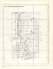
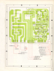
The stabilizer board once again. AWR-106.
(-) means you should expect a negative reading.

Pin 1 = (-)
Pin 2 =
Pin 8 =
Pin 6 =
Pin 7 =
Pin 9 =
Pin 10 =
Pin 11 =
Pin 13 =
Pin 14 = (-)
Pin 15 = (-)

Don'y worry about the diode's as yet. A good visual inspection is all that's needed for now.
HiFi Engine has a fairly good service manual to follow.
https://www.hifiengine.com/manual-library.shtml
The site is free, required is to sign up. It's a safe site and won't bother you with spam.

upload_2017-3-14_15-5-10.png
 
@zebulon1
Board 106
1 -32.2
2. 34.5
3 GND
4 .54
5. .56
6. 39.6
7. 10.4
8. 10.3
9. 9.7
10. 20.7
11. 41.1
12 Gnd
13. -41.3 maybe + dont remember if i put red to the pin or Black lol
14 -21.2
15 -43.2
 
The stabilizer voltages don't look too bad.
All are there and low due to the DBT drawing current.

Time to look at the Protection board voltages.
All the readings I'm asking for are in DC:
Black probe to Chassis ground.

Pin 1 =
Pin 2 =
Pin 3 =(-)
Pin 5 =
Pin 6 =
Pin 9 =

upload_2017-3-14_17-20-44.png
 
will if the big filter caps weren't bad one of them is now.. i went to get a smoke and came back and found the pioneer had the same thought one of the big filter caps was smoking and pouring electrolyte out nOW ive got a mess... the unit was on its side and now there is **** all over the connections
 
We (I) should of had you check the Voltage (AC and DC) on the cap terminals.
I'll send you some serviceable caps tonight.
Sorry we'er on hold until I can get you the caps.
 
It looks like you are making decent progress JS. You have great people giving you a hand. Quite a few years back, I had the idea that I would do the work my 1250. I bought all the parts from MTF's and mattsd's lists, but after ruining a few smaller projects, I decided that I was safer to send my beast to mattsd for the full Monty. Even with the added costs, I am fully satisfied I spent the money. A wise old inventor friend once told me that is was better to spend the money on the things you want because after a very short time you will no longer feel the pain from the financial loss. He was absolutely right.

I created a thread in which I tried to combine parts list and important quote regarding proper steps in repairing the 1250. In doing this, I found that keeping the parts list up to date was very difficult due to changing products on the market. That was the reason that I did not continue the thread.

Have fun with your Monster. It is so nice to have them back again when they are done. Keep an eye open for those pimples on the bottom of the filter caps. If you have the funds, I would advise replacing them, even if they test good. Just my opinion.
 
thanks for the advice... this receiver means a lot to me... it's not one i just picked up second hand, so i have had the thoughts of bite the bullet and send it off but I want to do it my self so bad because it was my dads and he was able to build amps do this stuff too... I feel its almost a rite of passage for me to get this right... He also gave me a Knight kit 35W stereo amp that he built in the 60's... it is in need of repair, and i'd like to restore it and give it to him for Christmas... but that thing is all Point to Point and i dont have schematics for it so I'm not ready to tackle that yet i don't think... Unless anyone knows anything about them.... I can start another thread if need be. I really enjoy this stuff... It's something i think i could do for a living if there was still a need for people to repair these awesome monsters and i had enough training and practice...
 
@zebulon1 i re installed new Filter caps (All 4)... cleaned up mess, plugged unit into DBT, and bulb is REAL bright, then immediately dims and 4 seconds later i hear the click.... if i shut unit off and turn back on light stays dim, doesnt get bright then dim down and no click... BUT if i leave unit off for 2-3 min it will act normal... almost like the big caps have to discharge some before it will work again or is it some sort of built in thing...
 
You can almost guarantee that it will take 10 seconds to numerous minutes for the caps to discharge. This is why it is suggested to use a resistor to discharge the caps before working on a piece of equipment. This is how I ruined my Pioneer SA-9500MkII. I turned it off and immediately started probing it without using minigrabbers on my meter. I crossed two contacts with the positive meter probe. I killed the outputs on the right side and spent months getting it back up to snuff. Be careful out there.
 
Update:
We been using the PM system to work on this 1250's issue.
Joe replaced the big filter cap that blew it's cookies and the replacement is only reading half of the twins voltage and getting hot.
Both amp boards have been disconnected.
Its narrowed down to the rectifier diodes on the stabilizer board, Pin one (1) for the S5151R diode.
He's removing the diode to check it for serviceability.

We should be discussing this on the forum as it seems a rare failure.
 
well im having some issues de soldering the rectifier diode, the solder is so heavy and so old my litlle solder sucker is having a hard time
 
desoldering the diode wire lead from the PC board or the metal strap from the pc board?

I don't think it's possible to desolder the diode from the metal strap.
 
Back
Top Bottom