• Please note that Audiokarma will be offline briefly for updates early on Monday morning, September 28th.

Another Super High End Phono Stage! No expense spared...

G'day all, just on the ESP P06 the circuit is designed to work well with practically any good dual op amp.

I suspect Rod rather likes the OPA2134, but he suggests the use of the NE5532 and even the venerable TL072 dual opamp as good choices in the P06 phono stage.

I have used OPA2314, NE5532, TL072, AD823 in my P06's, all with excellent results and with no errant behavior. Regards, Felix aka catman.
 
He (Rod) didn't use AD823's though, right?

It also could be that I am being too fussy as well as comparing them to the 640P which is known for having extremely low noise.

Jim you were right about me getting a new turntable before the DL-301 Mk2 arrives.:D
 
Could that rustling sound be opamp oscillation? Do the opamps get hot to the touch in the circuit? Do you notice an increase in the noise as you touch them?
I've read of this before and that it's usually in the ultra-sonic frequency range. OTOH I have no experience with it so may be talking out my arse! :yes:

Good point! I need to remember that I have o'scopes available when I work with these things.
 
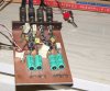
Latest PCB design incorporating input loading caps and new RIAA component adjustments:

Switched2opamp-1.jpg
 
If the board is going to a PCB fabrication shop, why not make it two-sided with a ground plane?

By the way -- there's an interesting discussion of preamp PCB design issues on the last two pages of the Russell paper linked above by quadtech: http://hifisonix.com/wordpress/wp-c...IAA-Equalization-Amplifiers_Part-One-V1.1.doc

I was keeping the cost down, it will add at least $5.00 to each board, I have built and tested the design on a PCB, it's as quiet as the P06 (the noise I noted can't be heard unless you have your ear against the speaker and is the same as the P06) which is on a proprietary PCB?

Would it make much difference as there is no hum at all especially since we are using batteries to power it?
 
I was keeping the cost down, it will add at least $5.00 to each board, I have built and tested the design on a PCB, it's as quiet as the P06 (the noise I noted can't be heard unless you have your ear against the speaker and is the same as the P06) which is on a proprietary PCB?

Would it make much difference as there is no hum at all especially since we are using batteries to power it?

Minimum ground system impedance is important in preamps even if power supply noise is absent. The benefits are many, including improved electromagnetic compatibility (EMC), enhanced op-amp stability, and distortion reduction. For audio circuits, I generally use two-layer PCBs with a top-side ground plane and all other connections on the bottom. If the layout isn't crowded, there will be plenty of metal to make the plane essentially continuous from an electrical point of view. It's a great deal less expensive than multilayer boards, and yields most of the benefit.
 
G'day all, I've long been an advocate of this 'low impedance' ground plane sort of electronics construction, very popular in Ham Radio RF work, for example.

Here is an example, generally referred to 'ugly' or 'dead bug' construction. This is actually a working ESP P06 phono stage that I built quite a few years ago.

No metal box, no additional shielding required. It looks 'terrible' :D but it works beautifully. :yes: Regards, Felix (vk4fuq) aka catman.
 

Attachments

  • working breadboarded P06  phono preamp..jpg
    working breadboarded P06 phono preamp..jpg
    56.5 KB · Views: 715
Last edited:
G'day all, I've long been an advocate of this 'low impedance' ground plane sort of electronics construction, very popular in Ham Radio RF work, for example.

Here is an example, generally referred to 'ugly' or 'dead bug' construction. This is actually a working ESP P06 phono stage that I built quite a few years ago.

No metal box, no additional shielding required. It looks 'terrible' :D but it works beautifully. :yes: Regards, Felix (vk4fuq) aka catman.

I just checked my Rod Elliot supplied ESP P06 PCB and it has no ground plane.

So I am in two minds because of the cost difference and the simple design we have running on batteries.

Felix do you think the ground plane one you built is better than the ones built on Rod's PCB's?
 
Here is an example, generally referred to 'ugly' or 'dead bug' construction. This is actually a working ESP P06 phono stage that I built quite a few years ago.

I use Dead Bug style for almost all breadboard work, including video. Works at least as well as a 'real' PCB -- probably better than many!
 
G'day all, in all honesty for audio work, a well designed pcb is probably as good as any approach, but for RF work the ugly construction/ low impedance ground plane approach is definitely preferable, I think. Regards, Felix aka catman.

Addition: The breadboarded P06 I built seems to have improved mains borne noise rejection and immunity, but apart from that the standard pcb version is equivalent, placed in a metal box and properly shielded.
 
Last edited:
mod to circuit

I would suggest that rather than send the L and R signal through the same chip that you employ each chip for only ONE channel signal. Crosstalk on small ICs is a more than a bit of a problem. By using each chip solely for one channel you lessen the possibility of crosstalk.

You will get better separation and a more "open" sound by keeping the two channels as logically and physically apart as possible.
 
My Dad was really into CB radios back in the 60s. I remember that one of the mods he had done was to add a ground plane. He special ordered a copper clad sheet of thin fiberglass, cut it to size, made some nylon spacers, and mounted it beneath the chassis of his CB rig, with the copper side down. Don't have any idea how helpful that was because I'm pretty sure it was a tube set, a Regency Imperial.

Question: How much benefit would this preamp design get from being grounded inside a metal chassis?

.
 
HipnoToad could you be so kind to post a simple b&w mirrored pcb design of your preamp as i want to etch myself with phototransfer technology ?
So far i've tested only the VSPS http://phonoclone.com/diy-pho5.html preamp wich sound quite ok but i want more than this.

Greetings from Bucharest!

Adrian
 
HipnoToad could you be so kind to post a simple b&w mirrored pcb design of your preamp as i want to etch myself with phototransfer technology ?
So far i've tested only the VSPS http://phonoclone.com/diy-pho5.html preamp wich sound quite ok but i want more than this.

Greetings from Bucharest!

Adrian

If you go here and download ExpressPCB I can email you the whole file so you can print out what you like.

http://www.expresspcb.com/ExpressPCBHtm/Download.htm

I just print out the bottom copper layer on shiny inkjet photo paper using a laser printer, it must be laser. And then use my wife's iron on the hottest setting for two minutes to iron it onto the copper clad. Then after it cools a bit dump it in warm soapy water and the paper peels off. It never fails, you can also touch it up with a permanent marker, but rarely necessary.

If you wish to use photo transfer you will have to flip it somehow. You don't have to do that using the iron on method.

Just let me know and I can email you the ExpressPCB file as an attachment.
 
My Dad was really into CB radios back in the 60s. I remember that one of the mods he had done was to add a ground plane. He special ordered a copper clad sheet of thin fiberglass, cut it to size, made some nylon spacers, and mounted it beneath the chassis of his CB rig, with the copper side down. Don't have any idea how helpful that was because I'm pretty sure it was a tube set, a Regency Imperial.

Question: How much benefit would this preamp design get from being grounded inside a metal chassis?

.


I think Felix, aka Catman addressed this when he said it would benefit from being in a grounded metal case, all audio circuits do IMO. Says me, who has four phono stages not in cases at the moment.:D


I would suggest that rather than send the L and R signal through the same chip that you employ each chip for only ONE channel signal. Crosstalk on small ICs is a more than a bit of a problem. By using each chip solely for one channel you lessen the possibility of crosstalk.

You will get better separation and a more "open" sound by keeping the two channels as logically and physically apart as possible.

Although I agree, this is a super cheap phono stage, and the sound is amazing already for what it is, it probably would make a difference but it might not be as much as you think.

Each time I make a change to the PCB I have to test it out, this change would entail making a whole new one and another batch of components and who is to say it won't create other problems.

Thanks for your input though, I do have a nice MC stage, two in fact in the works that use single circuit op amps but a little way off.
 
Last edited:
Back
Top Bottom