

You are using an out of date browser. It may not display this or other websites correctly.
You should upgrade or use an alternative browser.
You should upgrade or use an alternative browser.
Any Phase Linear Experts out there?
- Thread starter fdejong
- Start date

kconnor
Well-Known Member
I know of no practical method of measuring the transconductance of high current transistors without the use of a curve tracer. Curve tracers use pulsed signals when characterizing transconductance utilizing drain current measured in amperes versus microamps or milliamps. Steady state currents of the magnitude necessary to characterize this parameter in high current devices will yield invalid measurements due to heating. I could be wrong but I think the circuits you see for matching transistors are valid only for small signal devices. Such currents are too low to give a good indication of the overall transconductance of high power transistors.
It has been my experience that modern devices manufactured within the same date code perform so closely that it practically precludes the necessity for transistor matching.
It has been my experience that modern devices manufactured within the same date code perform so closely that it practically precludes the necessity for transistor matching.
Last edited:

P.L.F.
Active Member
It has been my experience that modern devices manufactured within the same date code perform so closely that it practically precludes the necessity for transistor matching.
Many thanks! That was my point, glad you reconfirmed.
Cheers
P.L.F.
Active Member
Phase Linear 700 series II - rewiring
I feel releone71 is just about to drop some new topics while progressing with his restoration P/L 700 II baby. Personally very much looking forward to it...
In the meantime I wish to come back to post #66 and address the point not really covered there - the amp rewiring. Easy to google a few examples of projects, where too much simplified factory grounding was effectively improved. A good example is here, doesn't matter so much that it actually referred to P/L D-500 II model: http://www.tomshardware.co.uk/forum/39810-32-redesign-carver-amplifier-phase-linear-corp.
I also had experienced hum problem while putting my all P/L gears into metal rack. After many experiments (isolating from the rack chassis, connecting to wall socket earth ground at the CD/DAC level only) I decided to interfere to the wiring of my first P/L amp. Attached is the conceptual drawing of what was done.
Any comments on this & other rewiring improvement are welcome!
Tx
I feel releone71 is just about to drop some new topics while progressing with his restoration P/L 700 II baby. Personally very much looking forward to it...
In the meantime I wish to come back to post #66 and address the point not really covered there - the amp rewiring. Easy to google a few examples of projects, where too much simplified factory grounding was effectively improved. A good example is here, doesn't matter so much that it actually referred to P/L D-500 II model: http://www.tomshardware.co.uk/forum/39810-32-redesign-carver-amplifier-phase-linear-corp.
I also had experienced hum problem while putting my all P/L gears into metal rack. After many experiments (isolating from the rack chassis, connecting to wall socket earth ground at the CD/DAC level only) I decided to interfere to the wiring of my first P/L amp. Attached is the conceptual drawing of what was done.
Any comments on this & other rewiring improvement are welcome!
Tx
Attachments

Last edited:


releone71
Active Member
Probably a stupid question, but how do I know if my PL 700 II is complementary topology or quasi complementary?
The practical way to know that is to remove the flexible plates between the fins of the heatsink in the back of the amp. The ones which cover the output transistors. If your outputs are 100% original you will see one row of Motorola TP9054 (or MJ15024) and one row of DB15025 (MJ15025) per channel, which are respectively the NPN and PNP type working in complementary topology. Otherwise you will see 4 rows of TP9054 (MJ15024) only, indicating you have a quasi complementary output stage. Be aware that, depending whether your amp is an early model or not, you could also find NEC devices in the back. In this case you will have alternatively one row of 2SD555 an one row of 2SB600 for the complementary topology, or 4 rows of the first type for the quasi complementary.
Last edited:
releone71
Active Member
Not yet, I'm still waiting for some other part I ordered from Mouser. But I will surely post some picture while the restoration is in progressI feel releone71 is just about to drop some new topics while progressing with his restoration P/L 700 II baby. Personally very much looking forward to it

WOW!! Your drawings are really precious, as usual, and your skill in finding useful posts in other forums are unmatched!!:thmbsp:In the meantime I wish to come back to post #66 and address the point not really covered there - the amp rewiring. Easy to google a few examples of projects, where too much simplified factory grounding was effectively improved. A good example is here, doesn't matter so much that it actually referred to P/L D-500 II model: http://www.tomshardware.co.uk/forum/39810-32-redesign-carver-amplifier-phase-linear-corp.
I also had experienced hum problem while putting my all P/L gears into metal rack. After many experiments (isolating from the rack chassis, connecting to wall socket earth ground at the CD/DAC level only) I decided to interfere to the wiring of my first P/L amp. Attached is the conceptual drawing of what was done.

Throwing in a few bits. One of the tests in the old Phase Linear manuals was a current sharing test, which called for measuring the current by looking at the signal across each of the output emitter resistors with a sine wave and a test load, and verify they were all within a certain range for each other (after a warm up period). Best practice was to match VBE's as close as possible, then verify performance. However, I haven't worked on these for over 30 years, so things may have changed.
P.L.F.
Active Member
Phase Linear 700 series II - current sharing test
Many tx for your comment! It is very clear now. And for the sake of precise meaning of P/L factory current sharing test, here is the procedure from the service manual:
[...] -> IMPORTANT: WHENEVER ANY OUTPUT TRANSISTOR HAS BEEN REPLACED IT IS NECESSARY TO PERFORM 'CURRENT SHARING TEST' TO VERIFY PROPER CURRENT SHARING OF ALL OUTPUT TRANSISTORS.
Current sharing test.
This test is necessary to verify that ALL outputs are operating properly, ensuring a permanent repair. Although the amplifier will probably meet all specs without all outputs operational, increased current loading of the remaining outputs will result in a significant reduction in reliability.
a) With an 8 ohm load connected to the output terminals of the left channel, drive the left input with a 200 Hz signal to obtain 53 V RMS output. Turn the line voltage down to 75 VAC.
b) Using DC voltmeter, measure the voltage drop across the emitter resistors in each output bank. Verify that there is between 150 mV and 180 mV DC across each resistor.
c) Replace any output transistor whose emitter resistor reading varies more than 20% from the typical; verify first that the resistor itself is not damaged. [...]
By all means an important step not to be skipped.
Still, a question that comes to my mind: for 230 VAC export amp version, do we need to turn down the line voltage to 150 VAC (to keep similar drop ratio)? Maybe better to observe the transformer secondary? If yes, what is the reading there if for the US amp version we reduce the line voltage on the primary to 75 VAC?
Any advice?
One of the tests in the old Phase Linear manuals was a current sharing test, which called for measuring the current by looking at the signal across each of the output emitter resistors with a sine wave and a test load, and verify they were all within a certain range for each other (after a warm up period). Best practice was to match VBE's as close as possible, then verify performance.
Many tx for your comment! It is very clear now. And for the sake of precise meaning of P/L factory current sharing test, here is the procedure from the service manual:
[...] -> IMPORTANT: WHENEVER ANY OUTPUT TRANSISTOR HAS BEEN REPLACED IT IS NECESSARY TO PERFORM 'CURRENT SHARING TEST' TO VERIFY PROPER CURRENT SHARING OF ALL OUTPUT TRANSISTORS.
Current sharing test.
This test is necessary to verify that ALL outputs are operating properly, ensuring a permanent repair. Although the amplifier will probably meet all specs without all outputs operational, increased current loading of the remaining outputs will result in a significant reduction in reliability.
a) With an 8 ohm load connected to the output terminals of the left channel, drive the left input with a 200 Hz signal to obtain 53 V RMS output. Turn the line voltage down to 75 VAC.
b) Using DC voltmeter, measure the voltage drop across the emitter resistors in each output bank. Verify that there is between 150 mV and 180 mV DC across each resistor.
c) Replace any output transistor whose emitter resistor reading varies more than 20% from the typical; verify first that the resistor itself is not damaged. [...]
By all means an important step not to be skipped.
Still, a question that comes to my mind: for 230 VAC export amp version, do we need to turn down the line voltage to 150 VAC (to keep similar drop ratio)? Maybe better to observe the transformer secondary? If yes, what is the reading there if for the US amp version we reduce the line voltage on the primary to 75 VAC?
Any advice?
Last edited:

laatsch55
Super Member
I believe thats correct. And really its not that critical, the idea is to drive it to clipping then by turning down the line voltage the current has to come up to deliver the same power. Doing it this way assures that the amp is loaded enough that ALL OPERABLE outputs will be joining the party.
My best guess is that they have you drop the line voltage to cut down output dissipation. The heat sinking required for full output is more than the heatsinks can accommodate. (BTW, when the IHF instituted rigorous power testing requirements in the 70's, both Phase Linear and Crown came out with Strap-on heatsinks to pass the power requirements.) So AFAIK, you should drop the voltage for 230 volts 150 Volts.
P.L.F.
Active Member
Phase Linear PL36 board wiring
Thank you Guys! That's clear now.
The manual didn't say about the right channel at all, but I guess we can confirm here the current sharing test goes the same way for the other channel too.
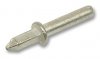
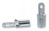
Changing the topic - I spent whole day trying to locate an annoying symptom of one channel disappearing from time to time in PL 400 series II of a friend of mine. I've found out a different way of PL36 wiring of driver board in compare with 700 II models I saw. On the board there there were pins like on the picture attached (cannot take a photo of the whole board now as I gave the gear back to its owner) and all connecting cables had a kind of socket - also see an example below. Strange. Don't think it was done at Lynnwood, although the serial number ASAIR was high (fully complementary output). After some examinations it came out that one of the pins on the input was causing a similar issue as cold solder and therefore gave the malfunction (not permanent though). I used DeoX to improve contacts and slightly tightened all these sockets but still thinking that maybe I should re-solder all the wires as in my PL 700 II?
What do you think? Have you seen that way of PL36 wiring? Can this be reliable enough in long term? Is the advantage of quick disassembly / replacement of the whole PL36 board worth of the change?
Tx for sharing your views!
Thank you Guys! That's clear now.
The manual didn't say about the right channel at all, but I guess we can confirm here the current sharing test goes the same way for the other channel too.
Changing the topic - I spent whole day trying to locate an annoying symptom of one channel disappearing from time to time in PL 400 series II of a friend of mine. I've found out a different way of PL36 wiring of driver board in compare with 700 II models I saw. On the board there there were pins like on the picture attached (cannot take a photo of the whole board now as I gave the gear back to its owner) and all connecting cables had a kind of socket - also see an example below. Strange. Don't think it was done at Lynnwood, although the serial number ASAIR was high (fully complementary output). After some examinations it came out that one of the pins on the input was causing a similar issue as cold solder and therefore gave the malfunction (not permanent though). I used DeoX to improve contacts and slightly tightened all these sockets but still thinking that maybe I should re-solder all the wires as in my PL 700 II?
What do you think? Have you seen that way of PL36 wiring? Can this be reliable enough in long term? Is the advantage of quick disassembly / replacement of the whole PL36 board worth of the change?
Tx for sharing your views!
Attachments

2n3403
No intent to hijack the thread, but I wanted to throw out an idea.
The bias circuit on all of the amps uses a 2N3403 for thermal tracking. It has a small heatsink to allow it to be mounted to output heatsinks. There are two NTE replacements. Their difference is the pinout. I think the proper one is 192A. It's nearly impossible to find the 3403. I have resorted to buying the 3403 without the heatsink and reusing the old heatsink which is a poor solution.
Another option may be an MJF15030G or MJF3055G. Both of these come in a TO220 package that has an isolated tab. Another advantage is the leads are larger and would be less likely to break. Looks like the 3055 is about $1.50.
Any comments?
No intent to hijack the thread, but I wanted to throw out an idea.
The bias circuit on all of the amps uses a 2N3403 for thermal tracking. It has a small heatsink to allow it to be mounted to output heatsinks. There are two NTE replacements. Their difference is the pinout. I think the proper one is 192A. It's nearly impossible to find the 3403. I have resorted to buying the 3403 without the heatsink and reusing the old heatsink which is a poor solution.
Another option may be an MJF15030G or MJF3055G. Both of these come in a TO220 package that has an isolated tab. Another advantage is the leads are larger and would be less likely to break. Looks like the 3055 is about $1.50.
Any comments?
Last edited:
laatsch55
Super Member
The last batch of 3403's I bought were from American Microsemiconductor at 6.00 each. I would not be opposed to trying the 3055, sounds like an excellent idea.
On a sidenote, after i tighten down the 3403's i take a small dab of epoxy and glue the high temp insulation that slides over the bare leads to the heatsink. This acts as a strain relief for the leads and has probably saved a half dozen trannies.
Just my 2 cents.
On a sidenote, after i tighten down the 3403's i take a small dab of epoxy and glue the high temp insulation that slides over the bare leads to the heatsink. This acts as a strain relief for the leads and has probably saved a half dozen trannies.
Just my 2 cents.
Last edited:
callab_gte_net
New Member
Don,
I have an good supply of Phase Linear factory original new old stock 2N3403's (with the "P" strap heatsink) available for a nominal fee. Please contact me at callab@gte.net
Ed
I have an good supply of Phase Linear factory original new old stock 2N3403's (with the "P" strap heatsink) available for a nominal fee. Please contact me at callab@gte.net
Ed
P.L.F.
Active Member
2N3403 replacement for PL700 sII
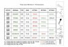
I saw only once a replacement of 2N3403 with TN6705A after a major repair, however with reused “P” type heatsink and pinouts connection inverted. It seems that 2SC3421 or BD139 are probably the best & generally available replacements, however in different package (TO126/TO255), therefore pinouts to be swapped too…
By the way, I wonder how often thermal tracking transistors go bust?
I saw only once a replacement of 2N3403 with TN6705A after a major repair, however with reused “P” type heatsink and pinouts connection inverted. It seems that 2SC3421 or BD139 are probably the best & generally available replacements, however in different package (TO126/TO255), therefore pinouts to be swapped too…
By the way, I wonder how often thermal tracking transistors go bust?
Attachments
Last edited:
P.L.F.
Active Member
2n3403 failures usually occur after several attempts to "reboot" with 20 amp fuses or foil around the fuses. Occasionally the leads break.
Thank you Don,
Good to know! From the moment I once discovered a solid paper-clip instead of the right fuse can expect virtually anything in the socket… I guess in Europe ANSI fuse standards are not that common, which may lead owners to ‘unlimited fantasy’ sometimes.
Regards