• The move to the new server is done. There are some software and database maintenance updates in process. This has us passing the hat around to help out. We appreciate any donations. Seriously, even a dollar helps. The payment page may be found here - https://www.audiokarma.org/support.html

Armstrong 626 troubleshooting problem

Hi Pablo

Sorry about the 'Pedro' in the last message.

In response to your recommended tests:
  1. I was able to get a good audio output with signal injection at the points you specified on both channels.
  2. Tracing the voltage from the input selector, it is 47.8V going into the selector switch and out again on the black line with phono selected. This goes into the PCB with the diodes and caps we have discussed. The voltage is 47.8 at the +ve side of the 39K resistor and 19.9V on the other side. It is still 19.9 when we get to the +ve side of the 100K resistors (one for each channel) but is only 6.3 and 6.5V on the other side of these resistors.
Something I noticed while I was making the tests is that two of the transistors on the board are different to the others. The schematic suggests that we should be seeing BC384L throughout. However, two of the transistors on the board are BC173C. These are on the same channel and look like the two transistors for the phono preamp for that channel. This makes me think they may have been replaced, although it is not otherwise obvious.

The point where you asked me to input signal was the input of another circuit board (which includes the tone controls, etc). The transistors immediately following are not BC 384L shown on the schematic but NP2N 3904 (I could only read one but they both looked the same). But it doesn't look like there is a problem on this board because there was good audio output with signal injection strait into this board.

Cheers, Jon
 
No problem about the name change, Jon; that was my father's name, so I tend to not notice it lol


Hi Pablo
  1. I was able to get a good audio output with signal injection at the points you specified on both channels
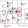
Since we did several tests already, please confirm this is the spot where you injected signal and got correct audio output on both channels:


Amp3.jpg


Something I noticed while I was making the tests is that two of the transistors on the board are different to the others. The schematic suggests that we should be seeing BC384L throughout. However, two of the transistors on the board are BC173C. These are on the same channel and look like the two transistors for the phono preamp for that channel. This makes me think they may have been replaced, although it is not otherwise obvious.

The point where you asked me to input signal was the input of another circuit board (which includes the tone controls, etc). The transistors immediately following are not BC 384L shown on the schematic but NP2N 3904 (I could only read one but they both looked the same). But it doesn't look like there is a problem on this board because there was good audio output with signal injection strait into this board.

Cheers, Jon
BC384L and 173C are pretty similar transistors; 2N3904 has a slight disadvantage gain wise. Shouldn't be a problem though.


Back to the input selector circuit, what's the voltage reading on the other diodes, anode side, when the corresponding input is selected? Do they also read around 6.5V?
 
I checked the point of signal injection and I'm no longer sure. It goes to the 2N3904 transistors via electrolytic capacitors. On second inspection, it looks like the caps may be 22 microF instead of 2.2 and there are a pair of 3.3K resistors, so I might have injected signal near the next downstream transistor. I will work this out and get back to you.

As for the voltage question - voltages vary slightly between measurements but this time I got a little over 7V at the anode side of one pair of diodes (the phono pair I think) and 0V at the cathode side of all 8 corresponding diodes.
 
I finally found the point you asked me to inject the signal into. The layout is quite confusing but in hindsight I could have found it from the mono control. Again, it was on the board with the tone controls etc, but in the opposite side to the other transistors. There was also a 0.22 microF cap instead of 2.2 in the schematic. This appears to be a bit of a theme.

There was no good audio on either channel. One was audible by distorted. The other was almost completely inaudible.

From the earlier signal injection I did by mistake, we know that the circuit seems to be functioning correctly from that downstream point.

I was not able to read the codes for the transistors close to where I fed in the signal but they looked similar to the BC173C type that were on the other circuit board with the diodes and caps.
 
Agree reading a unlabeled board could be a bit of a mess.

Jon, lets focus on the first transistor. Please read voltages on its terminals. We need to know if it's correctly polarized.


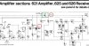
Amp5.jpg


Regarding those .22 caps in the signal path, guess someone screw it up. It couldn't have come that way from the factory. For example, the low frequency filter is a in line.22 cap. Just count how many of these are there -incorrectly- on that board.


.
 
Hi Pablo

I measured the voltages indicated in your last post. the result was 0V at all three points relative to the chassis. I checked the E-C resistance on the transistors but they measure OC.

I also re-checked the audio injection observations. At the correct injection point, the audio was as previously reported with the source selector at each of the four settings. However, the downstream injection point I used by mistake produced audio that was louder/better on one channel than the other this time.

Jon
 
0V..wow. R183 must be open or the solder points cold or burned.

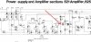
Check out the diagram and read that resistor value. If it reads 1.5K turn flip the board and check its solder points.


Amp6.jpg
 
Hi Pablo

The 1.5K resistor had indeed pulled away from the circuit board. The PCB is mounted by spring clips and one of them was applying pressure to the resistor, which with limited contact solder had become unattached.

The resistor has been re-soldered onto the PCB. This has restored voltages around the two transistors identified in your earlier message to approximately what they should be.

Signal injection at the point you recommended results in a strong left channel and a very week sound coming through both sides when the signal is injected into the other channel. This is the the same at the points I mistakenly input the signal earlier.

Cheers, Jon
 
Hi Pablo

I tried it after re-soldering the resistor and got nothing. But I tried it again after your message and now I get output on both channels. Also the radio appears to work. I was getting only one side on the radio at first and then the other side came in.

It looks like the unit is pretty much operational now.

Are we ready for me to install the multi-turn trim pots?

Jon
 
I'm sure there's a dirty switch on the channel that's acting a bit. Lubricate and work out all the switches.

Happy we finally found the issue. Still wondering about those capacitors in the signal path that appear to be wrong value...

You may change those 100 ohm preset resistors for multy turn trimpots. Set value in the middle before install.
 
I will go over the switches. I did some re-assembly for better testing and lost a channel again. I was getting one side on aux, tape and radio and also at the correct and mistaken signal injection points. Mono control did not restore sound to both sides.
 
Right again, Pablo. The issue seemed to come good with the loudness control - I hadn't paid as much attention to it because I didn't think it could make a channel drop out.

I will do the trim pots and adjust quiescent current. I read somewhere that the 20mA stated in the schematic was a maximum, so I may set to 10 or 15mA if it sounds OK.
 
I just was going to say a bad loudness switch could interrupt signal right at the pre output. Check out the diagram; that switch is feeding the volume pot. Cool this issue was just that.
 
Set the trimpots so you get 10mA and leave the amp at idle for 15min. Check out heatsink temperature. If it's not too warm you may increase bias very slowly, always allowing time for heatsink temp to stabilize. I'd say not let heatsink temp go above 40°C at idle
 
I thought we were almost done. It was producing good sound through Aux and Tape. The radio was working, although it was only coming through on one channel.

Then the earth return tripped. After that, the sound was low volume and muffled on both channels with input through Aux.

I hope whatever happened didn't do too much damage. I guess it stands to reason that the resistor wasn't responsible for leakage to earth.

Should I be concerned about having the amp powered? I'm not sure how to test function otherwise.
 
Don't worry, Jon. First inspect those clips holding the boards. Any of them may still be causing trouble.

If this is ok, proceed to re check all those voltages we were looking over: both power supply values, and the ones on each transistor.

Be careful not to short anything during the measurement.

Let me know.
 
Hi Pablo

It was looking good but there seem to be problems again.

I unclipped the circuit board (with tone control and the last two transistors before the power stage) and re-checked and all voltages - they were pretty much as before (ie about correct).

I injected signal at recommended point after input selector and again at input into power stage - all good. I then connected to the external input - Aux, Tape and Phono were all working. Radio was also working on both channels.

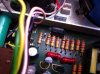
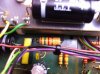
I replaced the paper insulators under the metal clips holding on the circuit board using shrink-insulation instead of the paper. These metal clips that are anchored to the chassis and clamp the PCB very close to components and PCB circuit lines. The old paper was not very flexible and appeared to put significant physical pressure on components it was in contact with. Perhaps the paper had become soiled and conductive - don't know. I've attached a couple of photos. There are still parts of the clips that are very close to circuit parts - interesting design choice.

Anyway, I was running it under observation and now its started blowing the output fuse on one of the channels. The first time this happened, it was exactly when I had pressed the button that changes between AM and FM presets. It has an earth connection but shouldn't do much. I replaced the paper insulation on this board before realising that the the speaker fuse had blown.

After replacing the output fuse, it blew again. The second replacement was 1A instead of 2.5 because I didn't have another spare - blew straight away. Seemed to be functional on both channels after replacing the blown blown fuse the first time.

I will get some replacement fuses so I can keep looking at the power stage.

Cheers, Jon
 

Attachments

  • IMG_0363.JPG
    IMG_0363.JPG
    85.9 KB · Views: 11
  • IMG_0364.JPG
    IMG_0364.JPG
    77 KB · Views: 11
Jon, verify with your ohmmeter, and the amplifier off and with the 2.5A fuses removed, the 82V rail is not shorting out somewhere. Let know what reading you get on the offending channel.


Amp7.jpg
 
The figures seem to climb and plateau - probably caps charging.

The resistance gets to about 10K for the channel blowing fuses and gets to about 20K for the other channel.

I have some fuses and will check the quiescent current and see if there are other odd voltages on the power board.
 
Back
Top Bottom