

You are using an out of date browser. It may not display this or other websites correctly.
You should upgrade or use an alternative browser.
You should upgrade or use an alternative browser.
Armstrong 626 troubleshooting problem
- Thread starter audiogymp
- Start date
-
- Tags
- 626 armstrong armstrong 626 problem

6taafondo
Pablo
Jon, do not forget to read those 40636 out of the circuit. Please post the result here.
If fully determined bad, we need to know why this happened. You were getting good sound out of both channels when out of the blue one of them quit with blown outputs.
Could be one´s fault? Or something hidding in that channel board? (bad solder, resistor, etc).
We need to determine otherwise may happen again.
If fully determined bad, we need to know why this happened. You were getting good sound out of both channels when out of the blue one of them quit with blown outputs.
Could be one´s fault? Or something hidding in that channel board? (bad solder, resistor, etc).
We need to determine otherwise may happen again.
Hi Pablo
Here are my measurements for the 40636s after removal.
For the first 40636:
B+, E-: 463
B+, C-: 453
C+, E-: OC
B-, E+: OC
B-, C+: OC
C-, E+: 453
For the second 40636:
B+, E-: 464
B+, C-: 456
C+, E-: OC
B-, E+: OC
B-, C+: OC
C-, E+: 455
A bit less conduction between B and E, as would be expected when the 100 Ohm resistors are not in play.
As for your other question, I have to confess that I had the B and E terminals confused at one point. I was getting some strange voltages closer to the start (perhaps DBT-related) and was checking voltage at what I thought to be the emitters. I could have done something by mistake but this was a some days before the problem with blowing fuses. Another possible mistake was when I was setting the quiescent current. The 0.68 Ohm resistors (0.47 on the schematic) are very close together and the alligator clip might have bridged between the two resistors briefly.
Are there any other checks you recommend before installing the new transistors?
Cheers, Jon
Here are my measurements for the 40636s after removal.
For the first 40636:
B+, E-: 463
B+, C-: 453
C+, E-: OC
B-, E+: OC
B-, C+: OC
C-, E+: 453
For the second 40636:
B+, E-: 464
B+, C-: 456
C+, E-: OC
B-, E+: OC
B-, C+: OC
C-, E+: 455
A bit less conduction between B and E, as would be expected when the 100 Ohm resistors are not in play.
As for your other question, I have to confess that I had the B and E terminals confused at one point. I was getting some strange voltages closer to the start (perhaps DBT-related) and was checking voltage at what I thought to be the emitters. I could have done something by mistake but this was a some days before the problem with blowing fuses. Another possible mistake was when I was setting the quiescent current. The 0.68 Ohm resistors (0.47 on the schematic) are very close together and the alligator clip might have bridged between the two resistors briefly.
Are there any other checks you recommend before installing the new transistors?
Cheers, Jon
6taafondo
Pablo
For the first 40636:
B+, E-: 463 OK
B+, C-: 453 OK
C+, E-: OC OK
B-, E+: OC OK
B-, C+: OC OK
C-, E+: 453 BAD
For the second 40636:
B+, E-: 464 OK
B+, C-: 456 OK
C+, E-: OC OK
B-, E+: OC OK
B-, C+: OC OK
C-, E+: 455 BAD
Jon, what tells these transistors are bad is you get a E-C reading. On a good one you wouldn't get a reading regardless of meter probe attachment.
Before installing the new transistors, I'd recommend checking every component in the power stage, being transistors, diodes, or resistors. This will only bring peace of mind. Do not remove any more components from the board, just measure them in place. Resistors will probably read lower than expected, at least some of them; that'd be normal. A bad resistor reads higher than expected. Suspect of a resistor reading even a little higher than expected (5% or more). Read all transistors and diodes and if in doubt (low or unexpected value) remove and read out of the circuit (remember setting meter in diode mode).
Once this channel runs again, I suggest switching the other channel output transistors to 2N3055 as well, so both run even. At least me, hate if both channels are not a mirror copy.
Hi Pablo
Sorry about the interruption - work called.
I checked the components on the bad channel of the power amp board in situ as best I could. I used a multimeter for the resistors and a component tester for the diodes/transistors. Some of the readings were obviously affected by making them in-circuit but in those cases, they were pretty much the same in the good and bad channels. None of the components looked obviously bad.
I then put in the new output transistors and tested. Same problem as before. I used a DBT to minimise damage - I hope this was not a mistake.
With both channels engaged (both power amp fuses in place), there was the usual surge as the caps filled. I bridged the 47 Ohm resistor across the thermal delay a few seconds after power-up. The bulb continued to glow lighter than expected. Fuse did not blow.
I then tried each channel separately by replacing one of the power amp fuses. With the good channel, the bulb settled to low glow after initial surge. With the bad channel, it was the same as with both fuses in place.
I them measure the resistance from the 82V rail from each channel to chassis, as before. 20K for the good channel; 19K for the bad one but it took a lot longer to plateau.
I then removed the transistor identified as 2N5320 in the schematic (actually an RCA 6178). Without DBT in place, the 82V rail got up to voltage and I got just under 40V at capacitor 481 - correct voltage. The fuse did not blow.
I tested the output transistors on the bad channel without removing any of the leads. OC from E-C on resistor measurement and over a volt on diode check.
It looks like there may something on the power amp board that I've missed. Can you think of any obvious culprits for the excess resting current.
Thanks, Jon
Sorry about the interruption - work called.
I checked the components on the bad channel of the power amp board in situ as best I could. I used a multimeter for the resistors and a component tester for the diodes/transistors. Some of the readings were obviously affected by making them in-circuit but in those cases, they were pretty much the same in the good and bad channels. None of the components looked obviously bad.
I then put in the new output transistors and tested. Same problem as before. I used a DBT to minimise damage - I hope this was not a mistake.
With both channels engaged (both power amp fuses in place), there was the usual surge as the caps filled. I bridged the 47 Ohm resistor across the thermal delay a few seconds after power-up. The bulb continued to glow lighter than expected. Fuse did not blow.
I then tried each channel separately by replacing one of the power amp fuses. With the good channel, the bulb settled to low glow after initial surge. With the bad channel, it was the same as with both fuses in place.
I them measure the resistance from the 82V rail from each channel to chassis, as before. 20K for the good channel; 19K for the bad one but it took a lot longer to plateau.
I then removed the transistor identified as 2N5320 in the schematic (actually an RCA 6178). Without DBT in place, the 82V rail got up to voltage and I got just under 40V at capacitor 481 - correct voltage. The fuse did not blow.
I tested the output transistors on the bad channel without removing any of the leads. OC from E-C on resistor measurement and over a volt on diode check.
It looks like there may something on the power amp board that I've missed. Can you think of any obvious culprits for the excess resting current.
Thanks, Jon
6taafondo
Pablo
Could be the bias (quiescent current) is set too high. If the fuse is not blowing (without inline DBT) now that's at least a good sign. Be very careful checking out bias; it's way easy to make a short with the meter probes. Attach them with the unit off. Do not use a DBT during this check.
Hi Pablo
Before putting the transistor I removed back into the circuit, I tested it with a component tester - photo of display attached. The tester didn't recognise it as a transistor but as two series diodes (apparently what a diode tester would tell you for an NPN). This kind of reading is reasonably common when testing a component in circuit, but the tester is generally able to identify transistors out of circuit and assign terminals.
Should I be concerned about this? I will hold off trying to set bias until you consider this reading.
Cheers, Jon
Before putting the transistor I removed back into the circuit, I tested it with a component tester - photo of display attached. The tester didn't recognise it as a transistor but as two series diodes (apparently what a diode tester would tell you for an NPN). This kind of reading is reasonably common when testing a component in circuit, but the tester is generally able to identify transistors out of circuit and assign terminals.
Should I be concerned about this? I will hold off trying to set bias until you consider this reading.
Cheers, Jon
Attachments
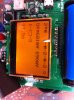
The resistance reading appears to be contradictory to the reading that identifies the component as two diodes. Based on the reading of diodes, terminals 1 and 3 would be C and E (or E and C) and you would not expect conduction between them. The 11.5 Ohm reading appears to be resistance between 1 and 3, suggesting that there is conduction.
I haven't been able to find a spec sheet that identifies the terminals of the transistor. I can try to work this out from the circuit and repeat tests using a diode test with the multimeter. Would this help?
I haven't been able to find a spec sheet that identifies the terminals of the transistor. I can try to work this out from the circuit and repeat tests using a diode test with the multimeter. Would this help?
Hi Pablo
There was an extra 12 Ohm resistor on the collector side (before the first 2.2K) but I'm pretty sure I was able to assign terminals. Readings below.
B+, E-: 555
B+, C-: 553
C+, E-: O/C
B-, E+: C/C
B-, C+: C/C
C-, E+: O/C
It looks like the transistor is bad after all. BD681 is a TO-126 type, NPN transistor that I can readily get. Is it a viable substitute?
Jon
There was an extra 12 Ohm resistor on the collector side (before the first 2.2K) but I'm pretty sure I was able to assign terminals. Readings below.
B+, E-: 555
B+, C-: 553
C+, E-: O/C
B-, E+: C/C
B-, C+: C/C
C-, E+: O/C
It looks like the transistor is bad after all. BD681 is a TO-126 type, NPN transistor that I can readily get. Is it a viable substitute?
Jon
My apologies, Pablo. I got my O/C and C/C back to front in my earlier post. It should be like this.
B+, E-: 555
B+, C-: 553
C+, E-: C/C
B-, E+: O/C
B-, C+: O/C
C-, E+: C/C
The readings were made with the transistor out of circuit both times. Looks like I'm getting E-C conduction both ways in this recent test, which is consistent with what the component tester was telling us.
B+, E-: 555
B+, C-: 553
C+, E-: C/C
B-, E+: O/C
B-, C+: O/C
C-, E+: C/C
The readings were made with the transistor out of circuit both times. Looks like I'm getting E-C conduction both ways in this recent test, which is consistent with what the component tester was telling us.
6taafondo
Pablo
Ah.. Ok, thanks for clarifying.
Jon, it'd be better if you stick to the 2N5320, otherwise you'd need to replace also its complementary 2N5322.
Check out this link below. Plenty of sources for it:
http://www.ebay.com/sch/i.html?_fro....TRC1.A0.H0.X2n5320.TRS0&_nkw=2n5320&_sacat=0
Jon, it'd be better if you stick to the 2N5320, otherwise you'd need to replace also its complementary 2N5322.
Check out this link below. Plenty of sources for it:
http://www.ebay.com/sch/i.html?_fro....TRC1.A0.H0.X2n5320.TRS0&_nkw=2n5320&_sacat=0
I'll order 10 Motorola parts from China, unless you think that's a bad idea. Postage from US is generally prohibitive for small orders. Some people on this forum warn about counterfeits from any but respected suppliers, like Mouser. If I order 10, it won't be such a problem if I get some that are no good.