• The move to the new server is done. There are some software and database maintenance updates in process. This has us passing the hat around to help out. We appreciate any donations. Seriously, even a dollar helps. The payment page may be found here - https://www.audiokarma.org/support.html

Armstrong 626 troubleshooting problem

Hi Pablo

Fuse is now going out straight on power-up.

I checked the unit to see if something conductive might have got caught up - there wasn't anything but I observed something else interesting.

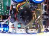
I've attached a photo of the power supply board and a closer shot of one of the fuse-like components. When the unit is switched off but connected to mains voltage I get a voltage reading from one of the two fuse-like things of mains voltage relative to the chassis. The other measures 0V relative to chassis. (It doesn't matter which side of them you measure from). There is also a low output from the bridge of about 0.6V.

I'm not sure what these components are. But it doesn't make sense that they could be seeing mains voltage with the unit switched off. In fact I'm not sure anything on the power supply board should be seeing mains voltage.

Jon
 

Attachments

  • IMG_0365.jpg
    IMG_0365.jpg
    117.9 KB · Views: 28
  • IMG_0366.jpg
    IMG_0366.jpg
    79.6 KB · Views: 23
To be sure, joggle the wires and boards a bit while the ohmmeter is connected. Perhaps something is close to shorting out somewhere.
 
Thanks to Rolf for the extra information. I was able to work out from the user manual and service guide what the two components on the power supply board were. Unfortunately, the service manual was concerned mostly with the radio and other specific tests and didn't include the circuit layout, so it doesn't seem to offer much assistance outside this specific issue.

The two fuse-like components looked unusual and similar and were aligned with symmetrical component groups and I assumed they were a pair - I can't see the traces on the power supply PCB without lifting it, which is not easy but I may have to do it. However, it now appears that one of the components is a mains fuse, called 'anti-surge' in the schematic. The other is a fuse on the regulated 45V output, that is not shown on the schematic.

Pablo, sorry about the bad info in my last post. However, the mains fuse is still seeing mains voltage with the power off, which it shouldn't. I will do the testing you suggest and see if it turns anything up. When I take the fuse out, there is mains voltage on one side (245V) and the other has about 180V AC. There is a capacitor (3 terminals) connected to the power switch and earth on the unit - could it cause this in ordinary operation or failure?

One of the legs on the mains fuse has come loose in the solder (the one measuring mains voltage without the fuse). I will need to re-solder this.

Jon
 
Pablo, I did the ohmmeter testing you suggested - joggling the wires made no difference.

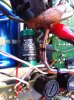
However, I had a look at how the power switch is wired, which explains why there is mains voltage in the unit with the power off. I've attached a drawing of the wiring at the power switch and what happens with the switch on/off. I've also attached a photo of the cap that is wired to the switch, as shown in the drawing.

I have to confess to being baffled that the unit would be wired so that it is constantly live with mains voltage. The effect of the power off appears to be to open the circuit only on the neutral line. This is not what the schematic shows.

I'm not sure this is connected to the issue with the power stage fuse blowing but I would like your opinion before moving on the the power stage again.
 

Attachments

  • IMG_0367.jpg
    IMG_0367.jpg
    39.6 KB · Views: 21
  • IMG_0369.jpg
    IMG_0369.jpg
    65 KB · Views: 21
Regarding those .22 caps in the signal path guys, again, you'll get far better low frequency response by replacing them with the value stated in the diagram (2.2uF). All of them except for the one on the low frequency filter. Indeed, I doubt that filter does anything as the low frequencies have already been filtered...

Jon, you drew a jumper between the switch contacts corresponding to the live mains wire. Is that jumper phisically there or is it the result of the resistance measurement? Whichever, the switch is probably bad either for being shorted inside, or due to not closing when pushed ON then it was jumpered. No issues, you can live with that. You just need to cut either (neutral, live, or both (as designed))

The cap on the power switch is to avoid contact sparking. Nothing else.
 
Thanks, Pablo

The live side of the switch has been jumpered - perhaps because of some fault with the switch. I'll look into it once I have the unit working, if it's OK to leave it for now (I may swap the live and neutral lines so that the live is cut and the neutral remains connected). I included information about the cap in case it might be an issue - I read a thread where someone had issues with ground leakage after lightning and this cap was causing leakage to earth. My measurements didn't show this happening but they weren't made under mains load.

Do you have any suggestions to work out why the fuse blowing for the power stage?

Jon
 
I don't think that cap is responsible for the earth issue, since it's not connected to earth. Could've been if it was.

Don't know what might be causing the PS fuse to blow; your resistance reading looks good, and joggling the wiring did not produced a short. I'd just try again with a good fuse. If continues to blow you'll have to start searching a bit deeper in the power amp stage.
 
Hi Pablo

The fuse continues to blow on power-up. Please let me know if you have run out of patience with this.

The only thing I can think of at this stage would be to put it on a DBT (shorting the thermal delay resistor) and check voltages on the plower board.

Thanks for all the help getting to this point, Jon

PS - the cap is connected to the earth. It has 3 leads connected to active, neutral and chassis, which is earthed.
 
Last edited:
Jon, I never run out of patience so don't worry about that. Interesting about the cap with 3 leads. You may disconnect its lead which is earthed for a while just to see if the differential mains switch keeps randomly tripping.

In the step above, where you tested resistance from the (82V) rail to chassis, where phisically did you attach the meter probe? Next to the power amp board, or on the PS? This is important. Please let me know as exactly as possible where the meter was connected.

I don't suggest the DBT since all voltages would go down without telling you more. Just be prepared to blow a couple more fuses but do not connect the DBT.
 
I measured between the chassis (the structural side of the unit) and either the downstream side of the fuses for each channel or the terminals on the power amp board that are directly connected to the fuses (it makes no difference).

I re-checked the resistance this morning and got about 19K for the bad channel and 20K for good channel. (Early morning here, so the amp was cooler than when last measured). In case it matters, the measurement on bad channel climbed over a period and the good channel stabilised quickly. I measured the good channel second, so if charging of the same caps was involved, they may have already been charged.
 
Jon, 20K is OK. Could it be the fuses you're using are incorrectly labeled?

Only extremely rarely a bipolar transistor would only read shorted when polarized (and open when not polarized). With this in mind, this one could be one of those rare occasions.

First off work out a bit the quiscent current pot and leave it centered. Test with a new fuse.

Then, I'd lift collector of 2N5320, or remove the transistor from the board, and test with a fuse. If keeps blowing, lift collector of the downstream transistor 40636, and check again.

Waiting for your findings.
 
The fuses are correct amperage but are fast-blow. Is this likely to be a problem?

I'm not sure I quite follow your recommendation with the quiescent current pot - should I dial it so that it measures 50 Ohm?
 
[URL='http://Hi Pablo']Hi Pablo[/URL]

Re-setting the quiescent current pot didn't stop the fuse blowing but when I removed the transistor in the position of 2N5320 in the schematic (actually 6178, E RCA 2J), the supply on the power amp board got up to voltage and the fuse didn't blow.

Jon
 
That's good to know, at least we know the power stage is indeed bad.

Please check out that transistor with the meter in diode mode, B-E, B-C, C-E, both forward and reverse bias. You also need to read both output ones 40636.

Let me know.
 
My measurements follow.

I assume the numbers my meter was giving me are mV.

I was not able to find a data sheet for the 6178 that showed the the ECB arrangement, so I have given the legs numbers, left-right with the transistor code facing up and legs towards me. (The 6178 was in place of the 2N5320 in the schematic and was removed from the board.)
1+, 2-: OC
1+, 3-: OC
2+, 3-: 558
1-, 2+: 553
1-, 3+: OC
2-, 3+: OC
From this, it appears that it is a functioning NPN transistor (the data sheet says it is NPN type). Leg 2 appears to be the base but I wasn't able to deduce which of the terminals were C and E.

I disconnected the C terminal at the power amp board for measurement of the 40636s. I'm not sure this was necessary.
For the first 40636:
B+, E-: 099
B+, C-: 412
C+, E-: OC
B-, E+: 099
B-, C+: OC
C-, E+: 452

For the second 40636:
B+, E-: 100
B+, C-: 412
C+, E-: OC
B-, E+: 100
B-, C+: OC
C-, E+: 449

The 40636s don't look right but they measure very close to each other. Am I right in thinking there has been an almost identical failure to them?
 
Agree, those look bad. Shouldn't be reading C-E either way. You'll be doing right by isolating them completely (or removing) to read again. Plus you'll be able to read B-E correctly. That 100 are resistors 223 and 225 in the diagram.
 
I will remove the transistors and confirm measurements once removed.

In the meantime, it looks like 40636 transistors are obsolete and I will need to order replacements. Are you able to suggest a reasonably common substitute?
 
Back
Top Bottom