• The move to the new server is done. There are some software and database maintenance updates in process. This has us passing the hat around to help out. We appreciate any donations. Seriously, even a dollar helps. The payment page may be found here - https://www.audiokarma.org/support.html

AU-D907 for restoration

Hyperion

Roobarb & Custard
Subscriber
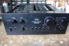
This is my latest on the bench for restoration, it has a few problems - just the normal stuff that's pretty much expected with a unit of this age.
IMG_3604a.jpg

It's new owner tried it out and found that one channel was not sounding good. The technician who had it first corrected a protection issue, but said that 'some of the Output Transistors are leaking' - whatever that means. So the owner retrieved it from the technician and brought it to me for a check over and this is what I found.

DC offset should be 0V +/-5mV
This amplifier
Left = 15mV
Right=145mV - there is an intermittent fault with this channel, tapping the main heatsink lightly causes this measurement to fly all over the place.

Bias should be 20mV +/-1mV
This amplifier
Left = 9.5mV
Right=0.1mV - this setting is also influenced by the intermittent fault as above.

I was able to adjust the above to just about acceptable readings, but only with great difficulty due to the condition of the trimmers and the intermittent fault.

Arising from the above, and of course the ubiquitous 'Black Flags', and 'Sansui Glue' the owner has requested a restore. It does have an original set of output transistors which seem to be ok, I'll be able to confirm this after I have made it safe to use.

This is the JDP version of the AU-919, so this will be number 4 of these that I have tackled, I am looking forward to getting into it. :thumbsup:

I will be copying much of Leestereo's AU-919 Restoration choices, plus a few little tweaks of my own. ;)
 
Last edited:
Register to hide this ad
Hmmm, leaky output issue. Me thinks you need to bring out the FLOMAX method of circuit repair as we cannot have incontinent Sansui amps prostating about poor sound :)
On a side note, since you have done several of these now do you have any tips on getting the boards out without tearing the whole amp down? Mine was a pita to get apart a few years back.
-Lee
 
since you have done several of these now do you have any tips on getting the boards out without tearing the whole amp down?
Sure. ;)

Driver Assembly comes out of the bottom after releasing 5 screws (4 for the heatsink and 1 ground tag) and pulling three connectors. The drive assembly can rest on a sheet of plywood big enough to easily cover the hole it came out of. ;)

Main PSU comes out if you pull 4 barrel connectors and desolder all connections - the ones on the underside can be reached after releasing 8 Main filter cap screws, and 1 ground tag screw.

Flat Amp comes out if you release the top strap (1 screw) and desolder 8 pin connections to the F-2846 Switching Board. This board and the F-2842 and F-2843 boards can also be released from the front panel with switch/pot shaft nuts and/or a few screws.

Regulated PSU comes out if you pull 3 barrel connectors and release one screw and 2 push rivets (just underneath the upright support plate) which secure a tag strip - this tag strip present on AU-919 but not present on AU-D907. Don't forget the C08 polarity issue ;)

Protection Board & MC Head Amp can both be accessed by dropping the rear panel and releasing as many wires as needed for access (not many).

MM Head Amp - is the difficult one, Remove support plate screws x4, Release the switch shaft from the front panel, and detach the rear panel sockets from the rear panel, and also remove the right side chassis member (2+4 screws). Probably wise to desolder the ribbon cables from the rear edge of this PCB too - be careful of the tracks, and the solid cores of the wire which is brittle and also bent flat to the track which is also a little fragile.

By doing the boards in a way that maintains the integrity of the chassis as you proceed, you can alleviate some of the pain of doing one of these. :D
 
Last edited:
I removed and tested the Black Flags from the Driver Board today, half of them tested as open circuit - just trace capacitance (~1pF) present. These value reductions are the knife edge that these amplifiers rest on, it doesn't take much to push them off.

Around 30 components removed for replacement so far, glue removal is progressing well. ;)
 
Last edited:
I completed the Driver Board yesterday - sorry no 'after' picture (yet), I'll take one if it needs to come out again. ;)

Here is a 'before' picture - or rather 'during' glue removal. Notice how (weirdly) all the Black Flags have been mounted on ceramic tubes! Most of the ones you can see are 3pF, the added lead length must take a bite out of the effectiveness of the 3pF capacitors, needless to say their C0G replacements did not re-use the ceramic tubes. ;)
IMG_3605a.jpg

Here is an 'after' picture for comparison.

IMG_3641a.jpg

It was easy to set up, or it would have been had I not been slowed down by that intermittent fault, which I am now almost certain is in the protection circuitry. Overall the behaviour of the protection circuit is so erratic I think there might be more than one fault. I also found that one channel of the as yet untouched Flat Amp was outputting just under 300mV at the test points, and in a replay of the unrestored Driver Board adjustment, this could be adjusted (thus indicating 'drift' but not a 'fault'), but some with difficulty. There are some 'factory looking' trackside component additions to the Flat Amp which I will take a picture of.

Someone who looked at this before decided to disconnect the main smoothing capacitors by chopping the cables at the main PSU end, so they are now likely to be too short to wrap properly, I might need to extend them a little. :(

I have decided to do the F-2841 Flat Amp next, a small board easy to remove and clean before restoration. ;) (after that the F-2840 Protection Board is next on the hit list - because it's made me cross! :D)
 
Last edited:
Just to confirm, John, pictures from you are always highly welcomed.

Some people, including myself, aren't very electronically-minded, but 'before and after' pictures on top of explanations help us understand and learn. You have an excellent track record here! :)
 
Notice how (weirdly) all the Black Flags have been mounted on ceramic tubes!
First thing I noticed, really weird and not done at the factory I would think. Didn't see anything like that on any of the boards of my JDP driverboards.
I see this D907 has the parallel/bypass films for the local filter capacitors. I am wondering if this was done only on D907 and not on the 919?
Glue isn't looking to bad. Do you use dissolvant to make it soft first or just afterwards for the remaining little spots?

There are some 'factory looking' trackside component additions to the Flat Amp which I will take a picture of

I am guessing these are the resistor-filmcap sculptures they made and not the extra polystyrene "black flags"
Edit: they are on the control board F2846:
20210620_175557.jpg

So now I am curious!
 
Last edited:
I have been breaking my mind about that. I think I have seen flat amp boards with 8 up to 14 polystyrene capacitors. All other components the same. Was one board less stable then others? Did they test them all in factory? And tune them one by one?
Or was this something that happened to change through time as they tried to get them more stable based on reports/repairs from customers.
 
Last edited:
Some pictures of the Flat Amp F-2841.

Topside after some component removal (6 electrolytics and a film capacitor), and glue cleaning.
IMG_3606a.jpg

Trackside - note 6 ceramic disk capacitors 4 x 3pF and 2 x 5pF +2 x 120KΩ resistors.
IMG_3608a.jpg

Topside stripped of components to be changed or have the glue cleaned off them.
IMG_3612a.jpg
On closer inspection I found one 2SA970 in the TR10 position, in the other channel is a 2SA992. So I removed the 2SA970 (hfe 245 !), and put in a 'previously enjoyed' 2SA992 (hfe 442 ;)). The leads were left very long on the '970, (possibly indicating service activity?) and with its low hfe I suspect it might have been counterfeit, not sure. I measured the Black Flags that came out of this board and 3 out of 4 were open. :(

I think there may have been more versions of this board - I've seen two - one of which had topside (vacant) positions for 2 x 5pF capacitors. It may well have been the case that Sansui were desperate to get these amplifiers more stable, and when a new board revision didn't solve it, out came the trackside modifications. :idea:

@GrisPato The picture you show of the F-2846 Board in post #14 is the same as my board - with two Zobel networks added untidily on the right hand side of the board (as viewed from the bottom).
 
Last edited:
The modern cell phone has been a cool addition to my bench habits. The camera resolution allows a quick photo as boards are ready to come out for wiring location detail as well as a visual documentation of the Sansui board modifications during manufacture. Sometimes those show on the schematic, sometimes they don't.
 
I have discovered that the added trackside components are present on the schematic, so these additions will stay, but will obviously be upgraded along with the other parts. It suggests this is an older revision of the board, as the ones I have seen so far have had no trackside additions.

See added picture in post #17 and additional notes regarding a lone replaced transistor. ;)

Update:
I am waiting on parts now, so it will be a couple of days before the next update.
 
Last edited:
Here is the rebuilt F-2841 Flat Amp. During the process I got rid of four 2SC1312's replacing them with hfe matched KSC1845's

IMG_3613a.jpg


And a view of the trackside factory modifications that have now been updated with new components. The soldering on this board doesn't look too good, but it's just a trick of the light, and while they could be neater I am satisfied that the joints are sound.

IMG_3614a.jpg

I got the board set up very easily, and it settled to a stable level of DC offset after a few minutes, I expect this to improve when I have restored the +/- 40V regulated PSU.

Protection Circuit intermittent fault.
I think I found the problem with the protection circuit, C01 on the protection board seemed like it might have been close enough to its support plate to be intermittently shorting on it, I've moved it away and no more funnies with the protection circuit. ;)
 
Last edited:
Looking good. Almost a miracle these days to be able to get the components you need/want.

four 2SC1312's replacing them with hfe matched KSC1845

I am still really hesitant to change them. Still not understand why Sansui did not use the 2sc1845 there when they clearly could have ( they use them on the same board in other positions ).
Assuming they had a good reason for it, or was it just to get rid of some old stock?
 
Back
Top Bottom