

You are using an out of date browser. It may not display this or other websites correctly.
You should upgrade or use an alternative browser.
You should upgrade or use an alternative browser.
AU-D907 for restoration
- Thread starter Hyperion
- Start date
-
- Tags
- au-919 restoration

GrisPato
Super Member
So this means your components arrived? Or just preparation?And moving on...
You're coming with me!
View attachment 2433019
And about 1½ hours later we have this...
View attachment 2433020

It's a lot of work to get that board out.
I kept it in. Just removed dual caps, ground screws, pre-powersupply board and the E-I transformer to be able to turn it freely. About the same time needed, just less desoldering.
Of course your way makes it a lot easier to work on. For me was really tentative moving the board but doable.
This accessing boards and glue removal is sometimes the bulk of the work
.I would guess one of the reasons normal repair shops don't want to do this work.

Parts arrived on 23rd December.So this means your components arrived?
- I could only finish the Flat Amp after these parts arrived.The Mouser order was picked and processed in a day and a half, it then spent over four days apparently waiting for Fedex to pick it up, and when I enquired about its status (to Mouser) it was here in less than two days.

It certainly is.It's a lot of work to get that board out.
Yep.This accessing boards and glue removal is sometimes the bulk of the work
Last edited:
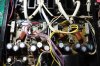
Cleaned and re-populated Main PSU Board.
I had to replace 8 resistors on this board as they were drowned in Sansui glue, everything else cleaned up ok.
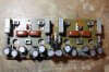
The reconditioned board now resident in the amplifier again.
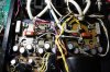
I needed my hot-rodded Weller with a number 9 bit (the hottest), for most of the rewiring on this board, not made any easier by the numpty that cut off some of the soldered connections. As you can see I mounted the bypass capacitors on the main board, as I couldn't see a good reason to put them back as they were, hanging in mid space between the terminals.
Power on test all good.
More pictures as the restore progresses.
I had to replace 8 resistors on this board as they were drowned in Sansui glue, everything else cleaned up ok.
The reconditioned board now resident in the amplifier again.
I needed my hot-rodded Weller with a number 9 bit (the hottest), for most of the rewiring on this board, not made any easier by the numpty that cut off some of the soldered connections. As you can see I mounted the bypass capacitors on the main board, as I couldn't see a good reason to put them back as they were, hanging in mid space between the terminals.
Power on test all good.
More pictures as the restore progresses.
Last edited:
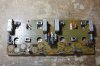
Next the +/-40V regulated PSU
Note the orientation of C07 & C08 the small pale blue electrolytics.

And rebuilt. (Note C07 & C08 replacements are inserted in the same orientation as originally, i.e. the opposite way round to the silk screen markings)

And re-installed.
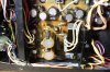
Power on tests are good.
Note the orientation of C07 & C08 the small pale blue electrolytics.
And rebuilt. (Note C07 & C08 replacements are inserted in the same orientation as originally, i.e. the opposite way round to the silk screen markings)
And re-installed.
Power on tests are good.
Last edited:
GrisPato
Super Member
I see you used the Nichicon UFW instead of UKW. Is this because of availability or there is not much between them?
Also noticed there is no glue under/around the capacitors on this board. You would expect some under the main ones at least.
So next up one of the bigger boards, driver or head amp or the smaller ones in the back, MC-headamp or protection?
I understand you did 3-4 of the AU-919/D907 by now. Some evolution in your approach? Do you do things different now then with the first ones?
Also noticed there is no glue under/around the capacitors on this board. You would expect some under the main ones at least.
So next up one of the bigger boards, driver or head amp or the smaller ones in the back, MC-headamp or protection?
I understand you did 3-4 of the AU-919/D907 by now. Some evolution in your approach? Do you do things different now then with the first ones?
Yes, primarily availability and luckily hardly any difference between them that I could see.I see you used the Nichicon UFW instead of UKW. Is this because of availability or there is not much between them?
The large capacitors were 3-legged, in other words they had an extra support pin so no need for 'Glue'.Also noticed there is no glue under/around the capacitors on this board. You would expect some under the main ones at least.
I'm pretty sure I'm going to do the MM Head Amp next, it'll be a tough one.So next up one of the bigger boards, driver or head amp or the smaller ones in the back, MC-headamp or protection?
The first one I did (my own) was by the book, no electrolytic value increases, just straightforward replacements. I have since gone through mine and applied much of the approach and changes described by Leestereo in his documented restore. I have also applied the Kuenhe modification to the MM Head Amp, and I'll be doing it to this one too.I understand you did 3-4 of the AU-919/D907 by now. Some evolution in your approach? Do you do things different now then with the first ones?
I did the +/- 40V PSU modifications to my one as a separate upgrade - I was totally gobsmacked by the improvement it made. I have done similar upgrades to other similar Sansui amplifiers with comparable results.
Last edited:
GrisPato
Super Member
I thought that too. But in the AU-D55X I restored the main capacitors also were 3-legged and they had glue under them.The large capacitors were 3-legged, in other words they had an extra support
But still sounds as a valid reason.
Kuenhe modification to the MM Head Amp
This I still have to look into, a little hesitant towards cutting traces. Maybe I should just do it.
GrisPato
Super Member
Yes, that one is a lot of workMM Head Amp next, it'll be a tough one
Making slow progress with the MM Head Amp.
This is the view of the board in question.

I have since detached the switch shaft, removed the lower (side) chassis member, de-soldered the two black ribbon cables, removed the heatsink and the support plate for the other end. I now have the board reasonably free and can work on it OK. I have been trying out the 'hairdryer method' for removing the Sansui glue, and so far it is working out very well, I don't remember who suggested it on here - but thank you whoever it was.
The first four Black Flags that came out of this board were once again all over the place. They should all have been 22pF and were 1.8pF, 23pF, 11pF, 5.7pF. I'll report on the others when I get to them.
This is the view of the board in question.
I have since detached the switch shaft, removed the lower (side) chassis member, de-soldered the two black ribbon cables, removed the heatsink and the support plate for the other end. I now have the board reasonably free and can work on it OK. I have been trying out the 'hairdryer method' for removing the Sansui glue, and so far it is working out very well, I don't remember who suggested it on here - but thank you
whoever it was. The first four Black Flags that came out of this board were once again all over the place. They should all have been 22pF and were 1.8pF, 23pF, 11pF, 5.7pF. I'll report on the others when I get to them.
Last edited:

Nice workmanship as always
This is the almost completed MM Head Amp, as sharp eyes may be able to see, one trimmer has yet to be replaced. (on order - eta tomorrow hopefully).
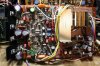
All glue has been removed, as have all Black Flags - which were a shambles when checked. Output transistors & PSU transistors have been remounted, heatsink compound refreshed. The 'Kuehne' modification has been done, thanks for your clearly documented info on this @lbcgav.
Something interesting, there were 3pF Black Flags where the schematic says they should be 6pF, but not to worry, some kind soul had added a 'Plain Jane' 3pF ceramic disk in parallel with each one on the track side. (the AU-919's I've seen definitely had 6pF Black flags in those positions). Naturally I have removed all the track side 3pF ceramic disk capacitors and replaced the 3pF+3pF combinations with C0G/NPO 6pF.
And sharp eyes might also notice that I put raised links in place of C55 & C56 (next to green ES bipolars), as it might come in handy to hang a voltmeter or an oscilloscope probe off them.
All glue has been removed, as have all Black Flags - which were a shambles when checked. Output transistors & PSU transistors have been remounted, heatsink compound refreshed. The 'Kuehne' modification has been done, thanks for your clearly documented info on this @lbcgav.
Something interesting, there were 3pF Black Flags where the schematic says they should be 6pF, but not to worry, some kind soul had added a 'Plain Jane' 3pF ceramic disk in parallel with each one on the track side.
(the AU-919's I've seen definitely had 6pF Black flags in those positions). Naturally I have removed all the track side 3pF ceramic disk capacitors and replaced the 3pF+3pF combinations with C0G/NPO 6pF.And sharp eyes might also notice that I put raised links in place of C55 & C56 (next to green ES bipolars), as it might come in handy to hang a voltmeter or an oscilloscope probe off them.
Last edited:

The first four Black Flags that came out of this board were once again all over the place. They should all have been 22pF and were 1.8pF, 23pF, 11pF, 5.7pF. I'll report on the others when I get to them.
Miserable things

Nice restoration so far sir
Completely unrelated, how is the supply of KSC1845's on your side of the pond?
-Lee
Thank You SirNice restoration so far sir
Regarding KSC1845, one of my preferred UK based suppliers has over 15,000 in stock.Completely unrelated, how is the supply of KSC1845's on your side of the pond?
Last edited:
I have been trying out the 'hairdryer method' for removing the Sansui glue, and so far it is working out very well, I don't remember who suggested it on here - but thank you
I read one like that, too. So, I started using an SMD hot air tool. You can direct the heat with it really well.

_mano
Well-Known Member
Yes, and their postal costs are still very/very reasonable.Thank You Sir
Regarding KSC1845, one of my preferred UK based suppliers has over 15,000 in stock.

Nice!This is the almost completed MM Head Amp, as sharp eyes may be able to see, one trimmer has yet to be replaced. (on order - eta tomorrow hopefully).
View attachment 2441546
All glue has been removed, as have all Black Flags - which were a shambles when checked. Output transistors & PSU transistors have been remounted, heatsink compound refreshed. The 'Kuehne' modification has been done, thanks for your clearly documented info on this @lbcgav.
Something interesting, there were 3pF Black Flags where the schematic says they should be 6pF, but not to worry, some kind soul had added a 'Plain Jane' 3pF ceramic disk in parallel with each one on the track side.
And sharp eyes might also notice that I put raised links in place of C55 & C56 (next to green ES bipolars), as it might come in handy to hang a voltmeter or an oscilloscope probe off them.

I finally got back to this after a domestic issue requiring my undivided attention.
I have now reassembled the MM Head Amp Board into the amplifier, DBT checks OK - DC offset adjustment OK too.
I just have a couple of issues I'd like to attend to around the amplifier before continuing, then I'll be onto the Protection Board and the MC Head Amp Board.
I have now reassembled the MM Head Amp Board into the amplifier, DBT checks OK - DC offset adjustment OK too.
I just have a couple of issues I'd like to attend to around the amplifier before continuing, then I'll be onto the Protection Board and the MC Head Amp Board.
I finally got back to this after a domestic issue requiring my undivided attention.
I have now reassembled the MM Head Amp Board into the amplifier, DBT checks OK - DC offset adjustment OK too.
I just have a couple of issues I'd like to attend to around the amplifier before continuing, then I'll be onto the Protection Board and the MC Head Amp Board.
Nice work, John! As usual!