• The move to the new server is done. There are some software and database maintenance updates in process. This has us passing the hat around to help out. We appreciate any donations. Seriously, even a dollar helps. The payment page may be found here - https://www.audiokarma.org/support.html

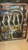
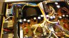
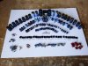
AU-D907 for restoration

Here is a view of the completed protection PCB.
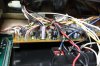
IMG_3637a.jpg

Quite a shy little board this one - tends to hide in amongst bunches of cables and its difficult to take good picture. :D

There are some track side components on this board too, which are in the schematic for the AU-919.

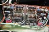
And a before picture of the MC Head Amp
IMG_3638a.jpg

Where it looks like someone has upgraded the 4 x 1µF 63V capacitors, they may be original? - but look like modern production to me.

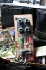
And an after view of the completed 'Power Amp Input/Output' board with a partial view of the completed MC Head Amp behind, (sorry no full picture of this).
IMG_3640a.jpg

Power on test good with and without DBT, +/-10V for MC Head Amp adjusted OK (after 4 resistor changes to accommodate the higher resistance trimmers).

Bench test good with signal generator, front panel cleaned and remounted, knobs cleaned - next - listening test. ;)
 
Listening test - Oh Yeah! - this is the AU-919 sound!

Runs as cool as a cucumber, just the chill taken out of the main heatsink, and sounds great. - very pleased with how this turned out. :banana:

A fantastic but very much expected result after such a thorough restoration. The passion and professionalism you put into this is admirable.

I can't wait to have it hooked it up at home for the next 40 years? Am pretty much sure this unit will outlast me after this restoration..

Great job John thank you!
 
I'll take a few days finalising this, I like to make sure everything is as 'tickety-boo' as possible before signalling its owner to come and collect it.

It is extremely quiet on all inputs even with the volume turned to maximum, except 'MC' where you can hear just a little hum due to the extreme sensitivity of this input, and that is with all the covers off!
 
Last edited:
A few notes for anyone else doing an AU-D907.

Driver Board
All the Black Flags were mounted on ceramic tubes (!). With the very low capacitances of the Black Flags, having even a centimetre of extra lead (on each leg) means that you are placing an inductance (albeit very small) in series with the capacitor thus lessening its effectiveness. It might have been done to reduce the amount of soldering heat reaching the sensitive Black Flags during manufacture of the boards? - who knows, anyway I removed all the ceramic tubes when replacing the Black Flags.

Flat Amp
I found a single 2SA970 on this board, which may have been fitted at the factory during testing? - just a guess. Anyway I fitted an original 2SA992 from my stash of used (but good) components. Some track side components on this board - which I upgraded in place exactly as they were.

Main PSU
There were four film capacitors wired point to point style on this board, so I remounted them on the PCB in the holes provided for 3 different film capacitor choices. It was worth the extra effort to completely remove this board as the Sansui Glue was pretty bad on this one.

Regulated PSU
The only problem here was that after restoration, even though I used a replacement 2% zener, the output voltages were a bit too high at +43.5V and -41.5V. There are some standard but unusual value resistors to set the output voltage (20KΩ, 24KΩ & 16KΩ), they all tested OK. So after some experimentation I decided to change R14 (16KΩ) to 15KΩ - I then got +41.5 & -40.4V - which is a much more acceptable result. Also two of the transistors TR02 & TR04 were not the types normally used TR02 was a 2SC1400 and TR04 was a 2SA750 (?) - nothing wrong with them, but I thought it odd enough to change them for the more usual types KSC1845 and a KSA992 respectively. (and I think both of those originally fitted transistor types are on the 'naughty list').

MM Head Amp
There were 3pF Black Flags where the schematic says they should be 6pF, someone had added 'Plain Jane' 3pF ceramic disks in parallel with each one on the track side. Naturally I have removed all the track side 3pF ceramic disk capacitors and replaced the 3pF+3pF combinations with C0G/NPO 6pF. The 'Kuehne' modification went OK on this one too, reducing the very drifty DC offset of this board to miniscule and stable amounts.

Protection PCB
I found that the Thyristor on this board wasn't the troublesome 2SF656, but an NEC F67XS, so I decided to leave it alone.

MC Head Amp
Having changed the 33KΩ trimmers for 50KΩ trimmers I found I couldn't adjust the +/- 10V required, and I did think about replacing the 33KΩ trimmers with a resistor for each, as seen in some AU-919's. However, after some checks I decided to change four 10KΩ resistors (in series with the trimmers) to 1KΩ, I could then adjust the +/-10V without difficulty.

(not done yet - a couple more pictures to post ;)).
 
@Hyperion John, I noticed in the photos of the MC Head Amp that there were four gray 100uF polar electrolytic caps toward the lower board edge. In the after, it appears that you replaced them with Nichicon UES bipolar electrolytic caps. Were these four the only ones? The after photo doesn’t show the entire board.
 
Back
Top Bottom