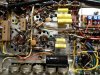
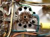
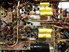
Development of the new power amplifier driver circuit is all finished now, and fully installed into Channel A. The Channel B driver circuit is still stock, and continues to act as a reference against which to measure the development work in Channel A. Next up, is digging into the Channel A 1st tone control amplifier stage to unlock some gain so that ultimately, the input sensitivity of Channel A will once again equal that of the stock design in Channel B. Once that portion of the modification is developed and installed, the unit then goes back into the listening room -- with Channel A now fully converted over to the new driver tube design, and Channel B still completely stock. With both mono and stereo sources then, the audible performance match between the two channels can be verified, which of course should be identical. Once that is proven out, then all of the modifications developed in Channel A for the new driver tube will be installed in Channel B, to complete this little side venture.
I would also offer that whereas so many of my previous threads and offerings have been singularly focused on (among other things) improving the performance of the original Fisher design, in this case, that took a back seat. Here, the goal was to as accurately as possible, mimic the performance characteristics of the original Fisher driver circuit with a new driver circuit, using a much more practical (for a whole host of reasons) tube to get the job done.
I am always very cognizant that all of these units are first and foremost "Fishers". While I believe that every unit I've modified has always retained its Fisher identity, some no doubt were really pushed in that regard when a number of old (useless) features were removed, new ones installed that were never originally there, and others were re-purposed for more practical use. Other units were modified with purely performance gains in mind, with no other goal sought, although dependability and tube life has always been a part of each and every modification.
For this project then, dependability is a key factor, as Rob apparently wants this unit to be operational into the next century. Adding a little extra kick, promoting cooler operating, and extending tube life are also key elements, which the addition of EFB will produce. But folks who love their Fishers that much love it first for the sound it produces, and are very protective of it. Therefore, open driver stage surgery can easily make them nervous -- wondering if such a significant modification will change the sound of the unit. As a result, as stated above, the goal of this particular portion of the project is to mimic the performance of the original driver circuit (when operating as intended) -- warts and all -- so that the original sonic signature will be maintained. As to the warts of the stock design -- it is somewhat over compensated, which helps to produce that lush Fisher sound that Fisher is famous for. Therefore, the new driver circuit is designed to achieve that same end. The end result came out very well, as the pics provided will show.
More as it unfolds.
Dave
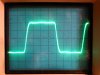
BELOW: These are 10 kHz square waves -- one from the new power amplifier design installed in Channel A, and one from the original stock design in Channel B. They are not perfectly identical, but these displays are more closely matched than many stereo amplifiers that (of course) have the same design in both channels. The new power amplifier design in Channel A is the top display:

BELOW: To show just how closely the two designs
are matched however, this shot has one trace from above placed perfectly on top of the other, showing that the rise time, transient response, and flatness of frequency response are all but identical between the two channels, in spite of one channel operating with the old 7199 driver design, and the other with the new 7247 driver:
BELOW: Underside view showing the new driver stage design fully installed in Channel A (closest to the rear of the unit where the level controls are):