• The move to the new server is done. There are some software and database maintenance updates in process. This has us passing the hat around to help out. We appreciate any donations. Seriously, even a dollar helps. The payment page may be found here - https://www.audiokarma.org/support.html

B-2 basket case incoming , Rott, might need some parts ;)

More dismantling of the B-2 . Right down to bare chassis .

Posting pics again for future reference when putting it all back together.

Same type screws I kept in one container, then for all others I used baggies and labeled them.

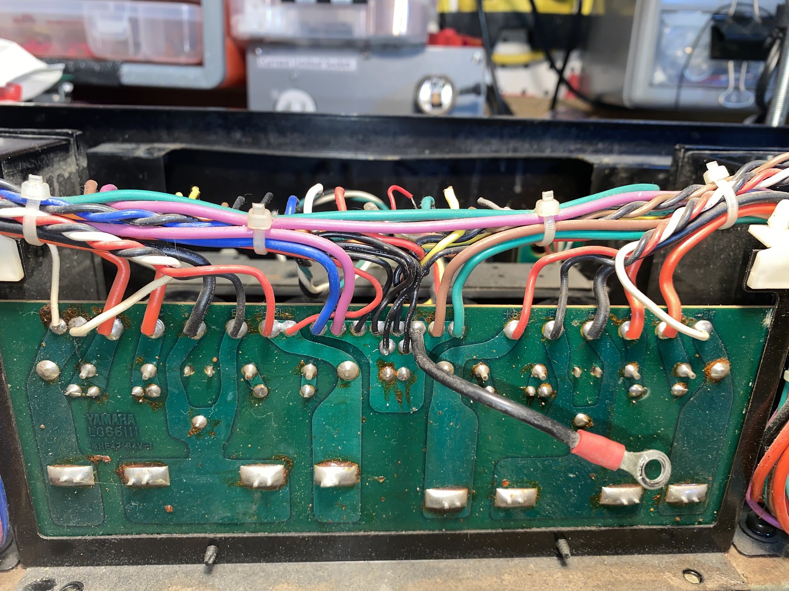
Main cap board connections.

52535079835_5df2ae99d5_h.jpg


Back Panel lowered then removed to access the mains input and aux socket removal and the other boards as well.

52536738034_e394716d6b_b.jpg


Socket removed from Transformer and mains in.

52536040867_1431c4c825_b.jpg


I was actually able to remove the power cable with out destroying the retaining clip!!

52537006905_f929323db9_b.jpg


Back plate De populated

52537013765_acf3541421_b.jpg


Input and meter input board.

52537096518_c9bc8af153_b.jpg


Question , I see many use new RCA's for the inputs, I actually like the originals. Is there another reason, then just personal preference, for changing them ?

Bare Chassis except for the meter's , those did come out after the pic.

52537145583_86cdff01a9_h.jpg


And I left a few boards connected to to the wiring harness including the transformers .

52536598606_8e8f2e8d75_h.jpg


Athanasios
At least one of your big filter caps leaked dielectric fluid.
 
At least one of your big filter caps leaked dielectric fluid.


Yeah looks like it, they all measured low as well. One was 16F and the rest were all under 12F .

The corrosion for the leak was worse near the right side and got under the transformer .

Athanasios
 
Yeah looks like it, they all measured low as well. One was 16F and the rest were all under 12F .

The corrosion for the leak was worse near the right side and got under the transformer .

Athanasios
The leak would me visible on the bottom side or if you desolder them.
 
This bottom or the the bottom once I desolder then big cans?

52528091159_e2ca9fe73c_h.jpg
Not that bottom
The physical bottom of the caps as they seat which would be the side or the bottom of that board from the caps side…. Where you would see where the leak came from before it spilled on that chassis
 
Not that bottom
The physical bottom of the caps as they seat which would be the side or the bottom of that board from the caps side…. Where you would see where the leak came from before it spilled on that chassis


Ok, I'll get to that this weekend.

Athanasios
 
Began working on this B-2 again and wanted to see if any of the original caps leaked.

This one in case seems to have some corrosion right where I think there is a vent under the rubber bottom

52701429946_b9b84ae186_b.jpg


What do you guys think?
All the caps were definitely out of spec from 11 to 12 farads .

Question for @rottalpha , for the rectifiers on the new cap board do you use isolators or just go straight to bare heat sink with paste? The heatsinks I got that you linked to have those thermal pads that need no paste. Should I use those?

52700980732_340cc15f9a_b.jpg


Athanasios
 
Last edited:
Began working on this B-2 again and wanted to see if any of the original caps leaked.

This one in case seems to have some corrosion right where I think here is a vent under the rubber bottom

52701429946_b9b84ae186_b.jpg


What do you guys think?
All the caps were definitely out of spec from 11 to 12 farads .

Question for @rottalpha , for the rectifiers on the new cap board do you use isolators or just go straight to bare heat sink with paste? The heatsinks I got that you linked to have those thermal pads that need no paste. Should I use those?

52700980732_340cc15f9a_b.jpg


Athanasios
bingo, that is a cap that **** the bed

As far as the heatsinks, no need to insulate.
Side note, as a habit, I mount all heatsinks ~1mm above the PCB. These here do not get hot but the ones for the TO-220 transistors in the regulated 12v supply and 85v supply, get hot. I know the boards are better now, but it does not hurt to be cautions...so that in 20 years the boards would likes just as good as the look today.
 
Thanks Pete, Yeah I thought that might be the electrolyte actually penetrating through the rubber bottom seal, pretty nasty stuff I take it if it can do that!

I guess I'll still use the pads instead of paste, just neater for me.

Athanasios
 
Nice work so far.

I love the top cover you took off that amp. What the hell....

That cover is about three times as heavy as the original!!! If it was done a little better I would have kept it, lots of air flow through it ! :D

lol

Athanasios
 
Today I installed the LKG's into the rectifier board , I would suggest doing one lug on each cap to allow for cooling, also do one side of that leg as well. Work on one side then flip the board and do the other side of each lug again skipping to the cap next door. This should prevent any heat damage , I decided to use my Hakko desolder gun as the heat source as it heats up faster and the job gets done quicker therefore subjecting the cap's to less time exposed to heat.

52702272847_43d4a474ff_b.jpg


Soldered in and lugs clipped .

52703112444_31dce50f18_b.jpg


Now on the the PSU ........

When ordering the parts from Mouser or Digikey make it easier on yourself and use the customer parts # reference window
to add the parts location . It will make installing that much faster instead of searching for the parts according to the BOM Pete provides. As shown below the KSC1815's go to Q 203,204,.....etc

52703152634_58f01934a8_h.jpg


Athanasios
 
Just started working on Pete's new PSU board and its already a pleasure to populate !!!
The large solder holes makes it easy for the solder flux and then the solder to flow down through
to the other sides solder pad , so there will be minimal touch up on the underside !!

Nice forethought Pete!!!

52702993251_9b8b3202c4_b.jpg


Solder just flowed through to other side with no problem!! Love it!1 Other boards I have worked on you almost always had to flip it over to get both sides to have solder on both the top and bottom pads.

52702993256_2922e9eb39_b.jpg


:thumbsup::thumbsup::thumbsup:

Nashou
It took a few iterations to get it better.
As far as components, very much everyone is marked in the silk screen.
 
It took a few iterations to get it better.
As far as components, very much everyone is marked in the silk screen.


Just finished all the resitors , took some photos before I cleaned off the liquid flux.

I think it looks awesome so far !!! :D

52703134776_a2444821bf_h.jpg


And what I call the "city scape street view"

52703621198_ef5d92a078_h.jpg


Crap R211 is little higher on the right side , need to fix that ! :p:)


Nashou
 
Last edited:
More work on the PSU, waiting to order some parts. I have all the 10uf caps in stock but not the 105 temp ones I would prefer to use and many are Nichicon FG's or Muse so not needed here I'd think.

I took the heat sinks from a Plasma TV I repaired years ago, then while adjusting the voltages it went kaput again, and I said F&%K it ! These heat sinks are nice and heavy .

I also need to get the inductors . Or I may use the originals, @rottalpha do the ones, you make or use , better and/or make a difference ? I was going to wind my own but don't have the right size magnet core wire I thought I had .

52713166437_2e2280f75a_h.jpg
 
Ok parts came in and board is complete !!

One cap I wasn't sure about as I never used them but choose them for a specific reason. I went with a Nichicon UBT series cap ( the light blue caps) for their high temp of 125 C° . These sit next to power resistors and may get exposed to some heat. Not sure if it was necessary but I decided to go that route .

52719926517_68169699d8_h.jpg


I also used the original inductors as stated above this post.

All thats left are the Fuses. I forgot if I ordered sockets or solder in fuses, have to search my pile of parts. :D

Athanasios
 
Last edited:
Back
Top Bottom