That's a really good tip about the using the locations in the customer part number. Just for reference, you should always try and avoid wherever possible soldering from the top and bottom side of a component joint as it risks flux entrapment in the solder joint. Sometimes I appreciate that heavy tracking or ground planes can make it difficult but worse case as long as you are getting flow though to about 75% of the board thickness then you will be fine. In most cases it will flow through without encountering this problem anyway. I always solder on the underside as it less likely to damage adjacent components.


You are using an out of date browser. It may not display this or other websites correctly.
You should upgrade or use an alternative browser.
You should upgrade or use an alternative browser.
B-2 basket case incoming , Rott, might need some parts ;)

The first prototype cap board came in for my other project the B1 and on it I added some 2SK43 to JFE2140 adaptor boards , it uses SMD header and the Texas instrument JFE2140 which I and one other member have used in the C4, and A1 preamp and Integrated amp respectively . I believe it will also work well here in the B2 drive board.
Here are some pics of it without and with the chip installed. I marked the Gate with a blue marking and the Drain with a white marking.
Just a mock up to make sure the header pin spacing is correct.

And it next to the original single connected with a heat sink 2SK43's

The Pin markings

Installed

Close up
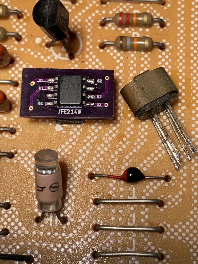
EDIT: Checking for good connection, both sides passed

Here are some pics of it without and with the chip installed. I marked the Gate with a blue marking and the Drain with a white marking.
Just a mock up to make sure the header pin spacing is correct.
And it next to the original single connected with a heat sink 2SK43's
The Pin markings
Installed
Close up
EDIT: Checking for good connection, both sides passed
Last edited:
Did a little work on this B2 driver boards . I decided to try to use the heat sinks that are designated for the main filter cap board that Pete makes. I had extras and I got them to fit. Added a protective sleeve on the collector pins.
I had to stager them a little different for the middle pair and end pair but they are somewhat symmetrical. The one is also reversed and I was actually able to drill a hole for its support, the other ones I could have but decided not too as they would have gone into traces for the collector and I dint want to go that route .

I had to stager them a little different for the middle pair and end pair but they are somewhat symmetrical. The one is also reversed and I was actually able to drill a hole for its support, the other ones I could have but decided not too as they would have gone into traces for the collector and I dint want to go that route .
Last edited:


Way cool thread & project. Just watching & learning. The extensive teardown and rebuild you're doing on that piece is incredible. Nice seeing folks with that level of skill set in this modern era of throw away electronics. I hope to get there one day.
My 2¢ here. I like the top cover. No one will notice in a cabinet. And it makes a great noodle strainer in the interim. Carry on gents.
My 2¢ here. I like the top cover. No one will notice in a cabinet. And it makes a great noodle strainer in the interim. Carry on gents.


The new trimpots came in and are the correct orientation and pin out .
Both boards are done, I also forgot the single 1885 diode and changed that with the soft recovery type. I did not change the three green caps in-between the driver transistors as the WIMA version probably wouldn't fit between the heat sinks I used .

And here is why you need to change any trimpot in any vintage gear you work on. This 2.2k trimpot had a total resistance of 2690 ohms , thats about 22% over its spec .

Athanasios
Both boards are done, I also forgot the single 1885 diode and changed that with the soft recovery type. I did not change the three green caps in-between the driver transistors as the WIMA version probably wouldn't fit between the heat sinks I used .
And here is why you need to change any trimpot in any vintage gear you work on. This 2.2k trimpot had a total resistance of 2690 ohms , thats about 22% over its spec .
Athanasios
Last edited:
Been a long time since I worked on gettin this back together. I had lots of work from the local record shop , I finished up a piece yesterday and told them I'm taking a break for a while doing any work for them. I need to get this and the B-1 projects done. Also life in general is getting in the way.
So today I did just a little work, Putting the Transformers back into the chassis and cleaning them before the installation.
Not much but it's something and on my main work bench so that will motivate me to push forward .

Remembering how everything goes back is going to be the hard part !! LOL
Surprisingly as bad as this unit was when I got it the transformers cleaned up very well.

I was going to twist the wires of the transformer, but to be honest I'm a bit lazy, and weary if there will be enough to reach the PS board. I know Pete does it, but a bit lazy as I said before . But who knows I may get motivation, stranger things have happened
Athanasios
So today I did just a little work, Putting the Transformers back into the chassis and cleaning them before the installation.
Not much but it's something and on my main work bench so that will motivate me to push forward .
Remembering how everything goes back is going to be the hard part !! LOL
Surprisingly as bad as this unit was when I got it the transformers cleaned up very well.
I was going to twist the wires of the transformer, but to be honest I'm a bit lazy, and weary if there will be enough to reach the PS board. I know Pete does it, but a bit lazy as I said before . But who knows I may get motivation, stranger things have happened
Athanasios
Last edited:
Ok Some progress today .
I removed the Old Switch board and installed the Main filter cap board as well as the power supply board.
Here are some pics, if you notice something is wired wrong please let me know . Its been so long since I took this all apart its easy to make mistakes reassembling .
Filter cap board pics .


And the power supply board, I still need to route the speaker wires . Question do you run the GND's over the board or under them guys?

Athanasios
I removed the Old Switch board and installed the Main filter cap board as well as the power supply board.
Here are some pics, if you notice something is wired wrong please let me know . Its been so long since I took this all apart its easy to make mistakes reassembling .
Filter cap board pics .
And the power supply board, I still need to route the speaker wires . Question do you run the GND's over the board or under them guys?
Athanasios
Yeah I'm not finished with the soldering. It was late and just wanted to get them "in there" as It was about 11pm and I had to get up at 5 am. Wanted to get finished so I could sleep with out any more thinking.the connecting wires to board color to location look OK. Not sure you would get an A on the solder joint quality tho
BTW, fill those solder pads that are made for different footprint components.
And will do on the open solder pads.
Is there a reason for that? Always been curious as to why manufactures do the same .
nashou

Asmodeus2112
Super Member
I thought the open pads got filled because they used wave soldering during factory assembly?Yeah I'm not finished with the soldering. It was late and just wanted to get them "in there" as It was about 11pm and I had to get up at 5 am. Wanted to get finished so I could sleep with out any more thinking.
And will do on the open solder pads.
Is there a reason for that? Always been curious as to why manufactures do the same .
nashou

yes and start twisting with the blue or brown wires, but I use new wires.Pete, for the speaker GND's do you run them over or under the board between the relays?
nashou
Asmodeus2112
Super Member
General thoughts on using crimp terms for wire to board?
Like these or similar?


Like these or similar?
Because it sits in the middle of the track and the track surface is reduced. Not saying the amp would not work. Comparing to the original design where the speaker signal was transferred via 0.5mm jumpers, this is an improvement no matter how you look at it. Note that those tracks are doubled up where possible plus they are 2oz copper.Yeah I'm not finished with the soldering. It was late and just wanted to get them "in there" as It was about 11pm and I had to get up at 5 am. Wanted to get finished so I could sleep with out any more thinking.
And will do on the open solder pads.
Is there a reason for that? Always been curious as to why manufactures do the same .
nashou
I think all Nashou needs to do, is to trim those wires back, get a fresh solder on the wire and resoled the connections. Unlike the original board, the size of the new board holes is very generous.General thoughts on using crimp terms for wire to board?
Like these or similar?
View attachment 3064106
View attachment 3064103
It looks like Nashou was tired and out of time to trim the old wires. Adding new wire crimp ends would take even more time.
I like to use wire-end connectors when applicable. Never used them for the B-2 for a very obvious reason: the wire must bend right at the top of the joint.
Ok, Got some parts in that I wanted to use for a new power cord. But I forgot how I marked the "Hot" side of the AC mains in as the cord I bought has the polarized blades for one of the two blades . I believe the narrow blade is the hot .
So in this pic of when I disassembled the unit I marked one of the wires with white out , So which is the hot @rottalpha ? the one I marked or the other?

Here is the cord and strain relief I am using .


Athanasios
So in this pic of when I disassembled the unit I marked one of the wires with white out , So which is the hot @rottalpha ? the one I marked or the other?
Here is the cord and strain relief I am using .
Athanasios
Take the old original cord and plug it in a US receptacle, then ask yourself: can it be reversed. And if yes, which side do you think Yamaha cared for us to plug in the hot?So which is the hot @rottalpha ? the one I marked or the other?
Now best practice: Hot to the fuse, then anything else......
Only reason I ask is from what I have read and past experience on these older units with non polarized plugs you can some times eliminate any hum that may be in the system just by flipping the plug. Reason is that you want to match the neutral to neutral etc .
This worked with a Technics Pre amp I had . So just wondering if it was the same for this amp.
Thanks
nashou
This worked with a Technics Pre amp I had . So just wondering if it was the same for this amp.
Thanks
nashou