• The move to the new server is done. There are some software and database maintenance updates in process. This has us passing the hat around to help out. We appreciate any donations. Seriously, even a dollar helps. The payment page may be found here - https://www.audiokarma.org/support.html

BA312 replacement

@bubhardy, by the way i never made an adapter for BA-312 before. What i did was an adapter for famous dual transistor 2SA798. Also i made small adapters for smt transistor to "through the hole".
On a separayte note : My condolences for your loss. This year also was difficult for me as my family also suffered very unexpected and very big loss which is basically a nightmare for a parent...

Den.
 
Last edited:
@bubhardy, by the way i never made an adapter for BA-312 before. What i did was an adapter for famous dual transistor 2SA798. Also i made small adapters for smt transistor to "through the hole".
On a separayte note : My condolences for your loss. This year also was difficult for me as my family also suffered very unexpected and very big loss which is basically a nightmare for a parent...

Den.

Thank you, Den! It’s nice to be home!

I understand that the TH version has it’s issues. I see at Mouser, a 7 pin, 0.1” (2.54mm) right angle breakaway header is only $0.20 in singles. A 36 pin strip would yield 5 each, and might be even cheaper.
I’ll have a look at your Gerbers. I’ve used JLBPCB several times, so I’m all set there.
Thanks!

Rick
 
Thank you, Den! It’s nice to be home!

I understand that the TH version has it’s issues. I see at Mouser, a 7 pin, 0.1” (2.54mm) right angle breakaway header is only $0.20 in singles. A 36 pin strip would yield 5 each, and might be even cheaper.
I’ll have a look at your Gerbers. I’ve used JLBPCB several times, so I’m all set there.
Thanks!

Rick
Feel free to let me know and we can adjust steps between the holes to precise distance to match the header. otherwise just attach 0.6-0.8 mm wire leads and it will be good enough. in the end it is very light and 7 leads of 0.6 mm in diameter wires will make it very stiff. besides this way you have a little flexibility ;)
 
Actually I just checked distance between the holes centers and they are aprox 2.5mm with a very little deviation but also keep in mind that hole diameter is 0.889mm
 
Hmm. 0.889mm is 0.035". The typical 0.025" square header pin is 0.035". I usually use a 0.042" hole in my PCB pads for these, so that's not going to work without opening the holes in the board a bit. I'd rather leave the board alone, even though it is single sided. I know that there are pin strips available to better fit the existing hole size, but they cost a lot more. So, I think your idea of using trimmed off leads is best here.
The pitch, if 2.5mm, would be off by 0.01" (0.254mm), if using a 2.54mm header. That is probably too much, too!
 
Hmm. 0.889mm is 0.035". The typical 0.025" square header pin is 0.035". I usually use a 0.042" hole in my PCB pads for these, so that's not going to work without opening the holes in the board a bit. I'd rather leave the board alone, even though it is single sided. I know that there are pin strips available to better fit the existing hole size, but they cost a lot more. So, I think your idea of using trimmed off leads is best here.
The pitch, if 2.5mm, would be off by 0.01" (0.254mm), if using a 2.54mm header. That is probably too much, too!
Actually I just took calculator and to my big surprise the distance between the holes is exactly 2.54mm. I made an adjustment for diameter 0.042''(1.0668mm)
 

Attachments

Last edited:
I am going to give this a try but I don't fully understand the schematic that Hipocrates published. R3 is shown as 51R and R4=180R. What does the "R" represent [ohms/k ohms]?
 
Here is corrected SMT adapter version for BA312 with exactly 2.54mm step between the pin holes with diameter 0.042'' :)
That’s great, TupolevFan! 0.1” is really what is expected, as it has been a default standard for many years.
Unfortunately, I have been tied up for about the last month. My wife’s mother passed away, out of state. Then, getting everything at home caught up, after being away for the better part of 2 weeks of that time. So I haven’t had much opportunity to work on this.
What I have in mind is a point-to-point sort of assembly, at first, just to confirm that it works. If it works, then I want to look at doing a small TH board. I know there is a narrow space on the board for the BA312. I am going to look at putting something together on a circuit board, with a straight header located on the bottom side, so that the board will sit above the components on either side of the space for the BA312. It will be shaped like a “T”, viewed on end, with the board being the horizontal cross of the “T”, and the header being the vertical shaft of the “T”. Of course, I need to get out my 9090 and have a look at the realities of where the BA312s are located, and their surrounding components.
I like the idea of using header pins, because they are fairly rigid, as opposed to solid core wire leads.
 
That’s great, TupolevFan! 0.1” is really what is expected, as it has been a default standard for many years.
Unfortunately, I have been tied up for about the last month. My wife’s mother passed away, out of state. Then, getting everything at home caught up, after being away for the better part of 2 weeks of that time. So I haven’t had much opportunity to work on this.
What I have in mind is a point-to-point sort of assembly, at first, just to confirm that it works. If it works, then I want to look at doing a small TH board. I know there is a narrow space on the board for the BA312. I am going to look at putting something together on a circuit board, with a straight header located on the bottom side, so that the board will sit above the components on either side of the space for the BA312. It will be shaped like a “T”, viewed on end, with the board being the horizontal cross of the “T”, and the header being the vertical shaft of the “T”. Of course, I need to get out my 9090 and have a look at the realities of where the BA312s are located, and their surrounding components.
I like the idea of using header pins, because they are fairly rigid, as opposed to solid core wire leads.
I know that 2.54 was standard i just was a bit lazy to calculate precise distance as i knew i was going to use just wire leads. let us know how it goes. I by the way in through the hole version deliberately put transistors at the top of assembly so they most likely would stick out above the other components
 
Tupolovfan, thanks for the clarification. I am going to try both. I have already uploaded the Gerber files and the boards are in production. I have a 9090 unit that is sort of an test-bed for some of my 9090 activities. There are two BA312's on the phono board [Equalizer F-2541] which has plenty of vertical clearance and two on the tone control PCB [F-2544 which is a little more crowded. I will do the through hole on the F-2541 and the SMD on the F-2544. I have had to track down working BA312's in the past and they are getting harder to find and I hate to cannibalize to find them. I have both boards in my parts inventory without the BA312 components. If these substitutes work out I will just use them instead. I am excited with this project.
 
Tupolovfan, thanks for the clarification. I am going to try both. I have already uploaded the Gerber files and the boards are in production. I have a 9090 unit that is sort of an test-bed for some of my 9090 activities. There are two BA312's on the phono board [Equalizer F-2541] which has plenty of vertical clearance and two on the tone control PCB [F-2544 which is a little more crowded. I will do the through hole on the F-2541 and the SMD on the F-2544. I have had to track down working BA312's in the past and they are getting harder to find and I hate to cannibalize to find them. I have both boards in my parts inventory without the BA312 components. If these substitutes work out I will just use them instead. I am excited with this project.
For SMT variant make sure you get transistors in SOT-23 package. as others are smaller i think. There are great Toshiba SMT transistors. Too bad 2SC3324BL is EOL. But there is a replacement. As I mentioned before i got myself fjv1845E (KSC1845E) from Rochester Electronics - 3600 of those just for 100 USD.
 
My proto boards came in and they are excellent quality (and inexpensive). The pin spacing is perfect so I think these PCB's have a great potential.

IMG_0431.JPG

Check out the pin spacing spot on.

IMG_0432.JPG

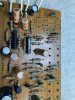
The BA312's here are on a tone control board which would be the most cramped spot on a 9090. The SMD version will easily fit here. The through pin version would fit also but I like the SMS version here as the appearance is much nicer. A note on parts. All the resistors for the through pin board I have or are on the way from Mouser but the 5.0 kohm SMD resistor is nowhere to be found in stock and 28 week lead time if you want to buy large quantities (1K -5K), but 4.7 kohm are plentiful. Could a 4.7 kohm substitute for R1 in this application. I could fit a through hole for this resistor but would like to keep the SMD board consistent.

Another thing to toss out. I can only test this board by pulling the BA312 from my bench unit and replacing with the prototypes and see if things work on a Go/No Go basis. I don't have anything/knowledge to do any quantitative testing. Any suggestions?
 
4.7k will be just fine. And you're pretty safe to just give it a go, I can't imagine it would damage anything - as long as there are no shorts - so check that.

I'm going to see if JLC PCB can make assembled ones of the SMD version, I'd put these in every unit I get!
 
My proto boards came in and they are excellent quality (and inexpensive). The pin spacing is perfect so I think these PCB's have a great potential.

View attachment 2378453

Check out the pin spacing spot on.

View attachment 2378454

The BA312's here are on a tone control board which would be the most cramped spot on a 9090. The SMD version will easily fit here. The through pin version would fit also but I like the SMS version here as the appearance is much nicer. A note on parts. All the resistors for the through pin board I have or are on the way from Mouser but the 5.0 kohm SMD resistor is nowhere to be found in stock and 28 week lead time if you want to buy large quantities (1K -5K), but 4.7 kohm are plentiful. Could a 4.7 kohm substitute for R1 in this application. I could fit a through hole for this resistor but would like to keep the SMD board consistent.

Another thing to toss out. I can only test this board by pulling the BA312 from my bench unit and replacing with the prototypes and see if things work on a Go/No Go basis. I don't have anything/knowledge to do any quantitative testing. Any suggestions?


for SMD 5K
you can use this
https://www.digikey.com/en/products/detail/koa-speer-electronics-inc/RN73R2BTTD4991B25/9991929
or
this
https://www.digikey.com/en/products/detail/vishay-dale/TNPW12065K10BEEA/1607933
or this
https://www.digikey.com/en/products...oric-bc-components/SMM02040C4991FB300/7064874
or even this
https://www.digikey.com/en/products/detail/yageo/RT1206BRD075KL/5936961
 
Back
Top Bottom