• The move to the new server is done. There are some software and database maintenance updates in process. This has us passing the hat around to help out. We appreciate any donations. Seriously, even a dollar helps. The payment page may be found here - https://www.audiokarma.org/support.html

BA312 replacement

4.7k will be just fine. And you're pretty safe to just give it a go, I can't imagine it would damage anything - as long as there are no shorts - so check that.

I'm going to see if JLC PCB can make assembled ones of the SMD version, I'd put these in every unit I get!

Heck yeah!
 
TupolevFan, I was using the package size 1812 for the SMD resistors based upon miking the pads. I am somewhat limited in my SMD expertise so I based the package size on measuring the proto board. Is the 1206 form factor what the board is designed for? I ordered all resistors as 1812. I may have to reorder.
 
TupolevFan, I was using the package size 1812 for the SMD resistors based upon miking the pads. I am somewhat limited in my SMD expertise so I based the package size on measuring the proto board. Is the 1206 form factor what the board is designed for? I ordered all resistors as 1812. I may have to reorder.
.
Yes all resistors are for 1206 Package. Sorry for not mentioning this to you.
 
TupolevFan:
Thanks, no problem. I will reorder the 1206 package size. I have a feeling that if this works [and it should] this will be a popular item as a BA312 replacement. I will order the new components today. The Toshiba 2SC3324 shown as "available" but my order placed last week is showing backordered on my invoice. I do have some Onsemi FJV1845FMTF smd (SOT23-3) I might use.
 
TupolevFan:
Thanks, no problem. I will reorder the 1206 package size. I have a feeling that if this works [and it should] this will be a popular item as a BA312 replacement. I will order the new components today. The Toshiba 2SC3324 shown as "available" but my order placed last week is showing backordered on my invoice. I do have some Onsemi FJV1845FMTF smd (SOT23-3) I might use.
2SC3324 probably was backordered last week but i got my 1000 transistors this week and i ordered a month back. I do have quite a few 2sc3324bl and if you want can share some.
 
I could use 12. That would allow me to fabricate 4 smd devices for testing. I also have 1000 on order but don't know when I will get mine. How do you want to do this?
 
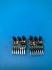
I have finished up two through pin versions of the proto BA312. The boards look pretty good but I learned a couple of things on these two. The first being the transistor pin outs are a consideration. The first two boards I used KSC1845 [ECB] transistors which required some pin bending to fit the board correctly, I plan to build the next board with ZTX694B [CBE] transistors which will line up better with the board. The CBE configuration of the ZTX will line up more naturally. The next observation is that resistors that are around 6mm in legnth are a very close fit and requires more effort to get them to mount. I have on order resistors in the 3.5mm long which I think will fit better. The header pins look a little off but I only had 3 pin and 4 pin in my inventory but 7 pins are on the way. I am waiting for SMD resistors for the SMD version of the board. Pics & testing to follow:

.IMG_0443.JPG IMG_0444.JPG
 
I have finished up two through pin versions of the proto BA312. The boards look pretty good but I learned a couple of things on these two. The first being the transistor pin outs are a consideration. The first two boards I used KSC1845 [ECB] transistors which required some pin bending to fit the board correctly, I plan to build the next board with ZTX694B [CBE] transistors which will line up better with the board. The CBE configuration of the ZTX will line up more naturally. The next observation is that resistors that are around 6mm in legnth are a very close fit and requires more effort to get them to mount. I have on order resistors in the 3.5mm long which I think will fit better. The header pins look a little off but I only had 3 pin and 4 pin in my inventory but 7 pins are on the way. I am waiting for SMD resistors for the SMD version of the board. Pics & testing to follow:

.View attachment 2382472 View attachment 2382475
Very nice.
The big question however remains. Do they work ? :))
 
I plan to test these on a Sansui 9090. There are two pair used on the 9090. One pair on the F-2541 [Equalizer Circuit Board] and on the F-2544 [Tone Control Board]. The schematic on the F-2541 shows the input to the BA312 is from the phono input jacks and gives some voltages to be found at pin 1,3,5,6,&7. The F-2544 has voltages at the same pins as the former but different. If I get these voltages and no audio artifacts I will consider the board a success. I will get the actual voltages from the OEM devices before I start as a baseline for the actual unit on which the testing will be done.
 
Just to keep those interested I am installing 7 pin SIP sockets on my test 9090. I will install the BA312 clones to test and will have some results/opinions to post sometime this weekend.

Looking forward to seeing the results. Was planning to build something based on that solution but you beat me to it :-)
 
Just to keep those interested I am installing 7 pin SIP sockets on my test 9090. I will install the BA312 clones to test and will have some results/opinions to post sometime this weekend.
I “air-wired” one up on a 7 pin 0.1” center header yesterday. It’s pretty ugly :bigok:! I’m not going to post a pic, it’s SO ugly. No matter, I’m going to replace the bad one in my 9090 and test it ASAP.
 
I got my 9090 out, to install my little BA312 airwired replacement, and prepared to confirm which channel had the bad one.
I discovered that the whole signal chain from S01, the selector switch, through S02, the tape copy switch, and onto the volume/balance pot, had issues on the right channel.
I WAS able to verify that the F-2544 right channel BA312 had no output.
But I have had to pause, and remove the switches and the pot for a thorough cleaning, as Skywatcher previously and patiently helped me with, on my 8080.
So, here is where I'm at-
IMG_6807.JPG
Hopefully, I will get a chance to work on these soon!
 
I just finished the evaluation of the BA312 clones both through hole and smd versions. Both types worked fine without any added noise or distortion. The test pcb is the F-2541 "Equalizer Circuit Board" and the BA312 IC's are the phono pre amps. I chose these to test since accessibility was decent and the phono pre-amp can be switched in and out from the rest of the tone control circuits for comparison of the noise floor.
IMG_0446.JPG

To begin the testing I checked the voltages with the OEM BA312 IC's to get a baseline on the pin IO per the Sansui Service Manual. I then installed 7 pin headers and tested the through hole BA312 "clones" then the SMD clones. The IC clones worked nicely and there was not any artifacts or distortion introduced into the signal path. I played a record alblum [Talking Heads "Stop making Sense"] to evaluate the playback. My subjective evaluation was that the phono playback was fully equal to the original BA312 playback. During the playback I took laser temperature readings of the 312 clones and surrounding components and temperatures were normally just above ambient room temperature. The subjective part of the test was certainly passing. I also took the voltage measurements of the original BA312's, Through Hole clone, and SMD clone. The table below shows what I consider identical performance of the clones to the original BA312's
 

Attachments

Another try on the voltage readings. I can't get the pdf to work. Hope this works. The voltages of both the OEM 312, Through Hole, and SMD are for all practical purposes identical. The clone pcb's are viable in my opinion and can be a reliable replacement for the BA312 IC.
 

Attachments

Back
Top Bottom