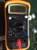
This is VR01 turned completely counter clockwise. VR02 is also completely counter clockwise. With both pots turned counter, the DBT lights, dims, then lights again and stays lit. If I adjust VR02, which will adjust, then turn the unit off, back on, the DBT flashes. VR01 will not change from 26And the left channel may be on 80 mV then


You are using an out of date browser. It may not display this or other websites correctly.
You should upgrade or use an alternative browser.
You should upgrade or use an alternative browser.
Barn find Sansui AU-7900
- Thread starter Kylek1443
- Start date

VR01 is the right channel according to the drawing. The output transistor/s is close to wide open. It's either blown or is being driven open by excessive bias. At this stage I would lift one end of R31 and R41 (this is removing the power supply from the bias network) then power up to see if the excessive current draw is reduced to zero.

GrisPato
Super Member
You have the DMM range in 20 V. So 0.26 is 260 mV. Interesting because up to now left-channel (vR1) bias would not adjust to above 8, which we can assume now was 80 mV. And now it will not go under 260 mV.
I am afraid to get any where with this you will have to get your head around what is happening when you adjust settings and replace components.
Example: I informed you to set the bias all the way down (adviced by Hyperion before after you mentioned the pulsing DBT).
Other example: I informed you about the range settings on your DMM for the resistance measurements. You did not reply, or even remeasured the resistors.
And I am not bashing you, believe me.
But for this to get to a positive ending you will have to check if what your doing is correct, and if you don't know, ask.
Counter clockwise as the starting point in bias settings implies the lowest possible value, so you turn clockwise to set it higher.
Does this mean this were the lowest values you could get it to or was the value going up turning the be clockwise? Make shure you can find the right information!
I am afraid to get any where with this you will have to get your head around what is happening when you adjust settings and replace components.
Example: I informed you to set the bias all the way down (adviced by Hyperion before after you mentioned the pulsing DBT).
Other example: I informed you about the range settings on your DMM for the resistance measurements. You did not reply, or even remeasured the resistors.
And I am not bashing you, believe me.
But for this to get to a positive ending you will have to check if what your doing is correct, and if you don't know, ask.
Counter clockwise as the starting point in bias settings implies the lowest possible value, so you turn clockwise to set it higher.
Does this mean this were the lowest values you could get it to or was the value going up turning the be clockwise? Make shure you can find the right information!
The output transistors were all just replaced with brand new ON T03s. So it must be driven by bias.VR01 is the right channel according to the drawing. The output transistor/s is close to wide open. It's either blown or is being driven open by excessive bias. At this stage I would lift one end of R31 and R41 (this is removing the power supply from the bias network) then power up to see if the excessive current draw is reduced to zero.
Not taking it personal. I only have so much time a day to test or try things. I try to ask questions when I’m confused. I recently had a chance to adjust the bias like Hyperion said. I hope you saw that. As for what you told me about measuring the resistors I just haven’t got to it yet. I apologize for not messaging you back on that.You have the DMM range in 20 V. So 0.26 is 260 mV. Interesting because up to now left-channel (vR1) bias would not adjust to above 8, which we can assume now was 80 mV. And now it will not go under 260 mV.
I am afraid to get any where with this you will have to get your head around what is happening when you adjust settings and replace components.
Example: I informed you to set the bias all the way down (adviced by Hyperion before after you mentioned the pulsing DBT).
Other example: I informed you about the range settings on your DMM for the resistance measurements. You did not reply, or even remeasured the resistors.
And I am not bashing you, believe me.
But for this to get to a positive ending you will have to check if what your doing is correct, and if you don't know, ask.
Counter clockwise as the starting point in bias settings implies the lowest possible value, so you turn clockwise to set it higher.
Does this mean this were the lowest values you could get it to or was the value going up turning the be clockwise? Make shure you can find the right information!
GrisPato
Super Member
I understand. Now let's just solve this.
With vr's turned counterclockwise the DBT is not pulsing but doesn't go dim neither, just less bright.
When setting the bias the DBT start pulsing. Logical in this case because you did set it to a current of around 80mA X 2 ((250 mA X 2) situation now) and 180 mA X 2, so more then 500 mA which would get the bulb pulsing.
So first thing try to set the bias from the counterclockwise position to approximately 10 mVolt. Make sure to range in correctly. If you get OL when on mVolt range just power it off and we will have to rethink.
Probably doing some measurements when you find the time.
Keep us posted
With vr's turned counterclockwise the DBT is not pulsing but doesn't go dim neither, just less bright.
When setting the bias the DBT start pulsing. Logical in this case because you did set it to a current of around 80mA X 2 ((250 mA X 2) situation now) and 180 mA X 2, so more then 500 mA which would get the bulb pulsing.
So first thing try to set the bias from the counterclockwise position to approximately 10 mVolt. Make sure to range in correctly. If you get OL when on mVolt range just power it off and we will have to rethink.
Probably doing some measurements when you find the time.
Keep us posted
Last edited:
GrisPato
Super Member
This was Hyperion advice on your questions: what to do ( turn the bias down)and should I take it of the DBT. ( Definitely not)Turn the bias down.
Definitely not.
This is what I meant. Take your time to read the advise and act accordingly.
This is what I’ve been trying to do. It’s on the DBT always, both pots turned all the way counter clockwise. I can get VR02 to change but VR01 is constantly stuck at the same number no matter what position it’s in.This was Hyperion advice on your questions: what to do ( turn the bias down)and should I take it of the DBT. ( Definitely not)
This is what I meant. Take your time to read the advise and act accordingly.
GrisPato
Super Member
Before when you adjusted it to the value 8, was it adjustable downward. Or was it this value and did not get higher.VR01 is constantly stuck at the same number no matter what position it’s in
Before when you adjusted it to the value 8, was it adjustable downward. Or was it this value and did not get higher.
ThaBefore when you adjusted it to the value 8, was it adjustable downward. Or was it this value and did not get higher.
forgive me that must’ve been a misunderstanding or a mistake on my part at the time. As of right now VR01 constantly reads 26. VR02 is adjustable but VR01 won’t budge from 26.Before when you adjusted it to the value 8, was it adjustable downward. Or was it this value and did not get higher.
Attachments

GrisPato
Super Member
Yes I understand this but he first time you tried to set the bias current and it did not go above 8 (which in this range setting is 80 mV) did you start below this value?Tha
forgive me that must’ve been a misunderstanding or a mistake on my part at the time. As of right now VR01 constantly reads 26. VR02 is adjustable but VR01 won’t budge from 26.
By the way, is the DBT pulsating now?
Mica on that transistor has been replaced. The DBT does different things depending on the way the bias is adjusted. When both pots are turned all the way CC, DBT lights, dims, then stays lit. When VR02 is adjusted higher, the DBT flashes AFTER unit is turned off then back on. VR01 does not move from 26 regardless of me turning the pot.And did you replace the broken mica under the driver transistor which could cause an unadjustable bias current?
I’ve been going back through the thread trying to catch up. I was wanting to start focusing on the pre driver transistors like you said. TR-11 to TR-14. What should they test at on the MM? I have to pull them out of the board?R46 is on the other side of the vr2 above tr14.
It is certainly possible that a capacitor somewhere on the deiverboard is leaking current. Is also possible it's a pre-driver transistor (tr12-14).
It can also be that one or more of the emitter or base resistors (r44-46-48-50-56-58-60-62-64-66) overloaded and is not good anymore ( resistance going up under load).
This can also be a reason for the low bias current.
So ideally you have to check all those components. Transistors preferably of board, resistors with one leg lifted if you get a weird reading ( lower then spec) and if they measure good preferably under load.
Be really care full not to short anything out.
Attachments


GrisPato
Super Member
Thing is. We could see there was a large current draw. We were assuming this was caused by something being wrong. And it was.
The bias current was/is much to high.
So now we know that we go from there.
First to see if we can get it down to 18 millivolt at least on one channel.
The other channels bias is not responding to the change of resistance from the vR.
You measure them (vR1 and vR2) to be able to rule them out for now.
Emitter resistors, you measure them so we are sure they are 0.47 Ohm if they are not the measurement we do in mVolt has to be recalculated.
The bias current was/is much to high.
So now we know that we go from there.
First to see if we can get it down to 18 millivolt at least on one channel.
The other channels bias is not responding to the change of resistance from the vR.
You measure them (vR1 and vR2) to be able to rule them out for now.
Emitter resistors, you measure them so we are sure they are 0.47 Ohm if they are not the measurement we do in mVolt has to be recalculated.
Ok first things first. Is this the correct setting for the MM? To measure the bias.First
Show a picture of the bias current on the good channel in mV.
Then measure the emitter resistors on the outputs. ( Power off, correct DMM range setting)
We go from there
Attachments

This is VR02. It stays steady around that number but the pot you turn is extremely touchyFirst
Show a picture of the bias current on the good channel in mV.
Then measure the emitter resistors on the outputs. ( Power off, correct DMM range setting)
We go from there