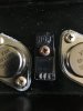
this one right here. I honestly feel like I cracked it when I installed it. It’s a new replacement mica. But I think I cracked it. It has silicone on both sides but I think it cracked when I tightened it. I have another replacement and I can redo the whole thing. I didn’t think much about it because it is on channel VR02 whereas VR01 wasn’t letting me get to 18V when adjusting the bias.It could for sure. Yep, go and replace it!
Did you put new ones in between?


You are using an out of date browser. It may not display this or other websites correctly.
You should upgrade or use an alternative browser.
You should upgrade or use an alternative browser.
Barn find Sansui AU-7900
- Thread starter Kylek1443
- Start date
I have to say, that is just not a dead short, but could be close.
Just another checklist:
This has to be done. And to be sure measure the outputs from case to heatsink to be sure they are well isolated.
Finding the faulty component is done by exclusion.
tried to post this but I don’t think it posted. This is the TR I’m talking about. I may have cracked the mica when I replaced it. If it could be a possibility I’ll replace the mica immediately.I am understanding that you mean the MJE15028/29 with power transistor?
It's called the driver transistor in a Darlington configuration.
Attachments


GrisPato
Super Member
Please make sure we have the correct information!!!
You mentioned before you could not set bias above 8mV for the right channel (vR2) later you say not for the left channel (vR1) and now again vR1.
So the problem of setting bias is in the left channel.
Besides, this can be two unrelated proems
You mentioned before you could not set bias above 8mV for the right channel (vR2) later you say not for the left channel (vR1) and now again vR1.
I have adjusted the bias. VR01 is at 18. But VR02 only goes to 10
Since VR01 is giving me low voltage and won’t raise higher than 8
didn’t think much about it because it is on channel VR02 whereas VR01 wasn’t letting me get to 18V when adjusting the bias.
So the problem of setting bias is in the left channel.
Besides, this can be two unrelated proems
I must’ve mistyped. The problem has alway been with VR01. I was able to set the bias for VR02. I might be slightly ignorant but it seems like the Sansui service manual for (Sansui F-2596) might be mirrored from the board I have. VR02 sets to 18, VR01 won’t go higher than 8ish. It sets between 7-8 Volts.Please make sure we have the correct information!!!
You mentioned before you could not set bias above 8mV for the right channel (vR2) later you say not for the left channel (vR1) and now again vR1.
So the problem of setting bias is in the left channel.
Besides, this can be two unrelated proems
Seems to me that the current clamp TR07/09 is doing it's job of protecting the output transistors. The bias seems to be excessive from TR01/03 or DC is getting in through C01/03 from the pre-amp...
Yes I followed the steps in the service manual. Turning both counterclockwise until it reached 18. VR02 went to 18, VR01 wouldn’t go higher than 10 and normally bounced between 7-9.Ok, clear.
Did you try already with both trimpots turned all the way down? (Bias value down)
. Give me a day or two and I’ll process this and test them. I’ll let you know what the MM saysSeems to me that the current clamp TR07/09 is doing it's job of protecting the output transistors. The bias seems to be excessive from TR01/03 or DC is getting in through C01/03 from the pre-amp...

BilboBaggins
Addicted Member
BTW, best if you use heat sink compound, and you need very little. That might be why the mica isolator cracked. basically, apply and spread a very tiny amount on each side of the mica and put it in place. In fact if there is too much, it is less effective.
For sure it is worth saving. And this thread is going to be invaluable for other hobbyists to learn from. Keep on it! You will get there!
For sure it is worth saving. And this thread is going to be invaluable for other hobbyists to learn from. Keep on it! You will get there!
Hypothetical question for you. C01 and C02 are 50v 1uf caps. But they are Orange colored. IF I were to replace them with new nichicons, would this be an acceptable replacement?Seems to me that the current clamp TR07/09 is doing it's job of protecting the output transistors. The bias seems to be excessive from TR01/03 or DC is getting in through C01/03 from the pre-amp...
Attachments
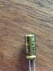
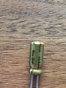

They would certainly 'work' as replacements, but you should understand that the orange capacitors like that are thought to be special 'low leakage' type, so a better choice would almost certainly be Nichicon KL, which are a modern low leakage alternative. You also have the opportunity to use a film capacitor in that position, like Wima MKS2 1µF, 50V for example, film capacitors are inherently low leakage, and the one I quoted is almost the same size as the original orange electrolytic.Hypothetical question for you. C01 and C02 are 50v 1uf caps. But they are Orange colored. IF I were to replace them with new nichicons, would this be an acceptable replacement?

Thank you for letting me know. I assumed there was some kind of special difference. At this point I just want to get the amp working for my friend. Who knows how much he will actually use it. It’s more of a sentimental thing for him because it belonged to his grandpa. Most likely it’s just going to sit unused 90% of the time. I know it sounds bad to not want to do everything completely “correct” but at this point, we just want it working.They would certainly 'work' as replacements, but you should understand that the orange capacitors like that are thought to be special 'low leakage' type, so a better choice would almost certainly be Nichicon KL, which are a modern low leakage alternative. You also have the opportunity to use a film capacitor in that position, like Wima MKS2 1µF, 50V for example, film capacitors are inherently low leakage, and the one I quoted is almost the same size as the original orange electrolytic.
GrisPato
Super Member
@DougBrewster
Thanks for helping.
The clamping, how does that work. I assume that is causing the pulsing of the DBT then?
I have been wondering about excessive bias current but because the bias voltage measured is so low and I don't know if the emitter resistors measure good I can not analyze that.
I had no idea that DC leakage on the input differential could cause something like this. Has to be a significant voltage then?
I welcome any help on this.
Seems to me that the current clamp TR07/09 is doing it's job of protecting the output transistors. The bias seems to be excessive from TR01/03 or DC is getting in through C01/03 from the pre-amp...
Thanks for helping.
The clamping, how does that work. I assume that is causing the pulsing of the DBT then?
I have been wondering about excessive bias current but because the bias voltage measured is so low and I don't know if the emitter resistors measure good I can not analyze that.
I had no idea that DC leakage on the input differential could cause something like this. Has to be a significant voltage then?
I welcome any help on this.
An emitter resistor that has gone high could also cause "apparently" high bias to appear at the base of TR07 or TR09 turning it/them on and clamping the drive/s to TR11/13 but I don't know if going high is a common failure mode for that kind of resistor. Worth checking though. When the clamp is imposed the bias drops and of course the DBT dims, then the clamp is released and the cycle repeats.
As far as C01/C03 is concerned it only needs leakage sufficient to forward bias the input network. I had that problem in a Rotel receiver I worked on a couple of years back; there had been a previous "event" and a cascade of damage had occurred including the input cap. Same fault symptoms as we are seeing here.
As far as C01/C03 is concerned it only needs leakage sufficient to forward bias the input network. I had that problem in a Rotel receiver I worked on a couple of years back; there had been a previous "event" and a cascade of damage had occurred including the input cap. Same fault symptoms as we are seeing here.
I’ve been going over trying to adjust the bias and seeing different things happen. In the manual it says turn both pots all the way counter clockwise. When I do this and turn it on, the DBT lights, dims, flashes, then comes to a steady light. Not super bright but the bulb is lit. Connecting to VR02, I can adjust the bias to 18 as stated in the manual (pictured). But when connecting to VR01, the readings are 26V and will not move regardless of pot adjustment. If I switch off the unit and turn it back on, the DBT flashes continuously. If I test either channel with the MM while the DBT is flashing the readings are all over the place.@DougBrewster
Thanks for helping.
The clamping, how does that work. I assume that is causing the pulsing of the DBT then?
I have been wondering about excessive bias current but because the bias voltage measured is so low and I don't know if the emitter resistors measure good I can not analyze that.
I had no idea that DC leakage on the input differential could cause something like this. Has to be a significant voltage then?
I welcome any help on this.
Attachments
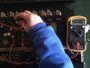
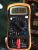
That picture is showing 180mV not 18
GrisPato
Super Member
Good find!!That picture is showing 180mV not 18
That is a high bias current ..
Class A
What’s my next move? Is this bad? I assume it’s bad.And the left channel may be on 80 mV then

Try to get it down to 18mV and then see where you are at. In operation the amp will see bias at least 10X idle current so you may have gotten away with it.