We are getting .437 both ways when measured at 2k ohms.Try with range set to 2 kOhm. Can be that both divisions are higher then 200 Ohm. The 4 ohm measurement is for the two leads connected with the track.


You are using an out of date browser. It may not display this or other websites correctly.
You should upgrade or use an alternative browser.
You should upgrade or use an alternative browser.
Barn find Sansui AU-7900
- Thread starter Kylek1443
- Start date
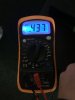
Do you think it could be the pot itself? Or is .437 ohms working? It’s definitely a problem on this channel?Try with range set to 2 kOhm. Can be that both divisions are higher then 200 Ohm. The 4 ohm measurement is for the two leads connected with the track.

GrisPato
Super Member
That looks ok. It's a 470 ohm variable resistor turned all the way to one side.
So although sometimes resistors can change value under load we are just going to assume for now the vR is good.
Next step.
I don't know how accessable the power board is for doing measurements with power on ( so the board installed )?
Can you measure the voltage from R29 to ground potential and from R30 to ground potential? On the high side ( towards the outputs)
So although sometimes resistors can change value under load we are just going to assume for now the vR is good.
Next step.
I don't know how accessable the power board is for doing measurements with power on ( so the board installed )?
Can you measure the voltage from R29 to ground potential and from R30 to ground potential? On the high side ( towards the outputs)
GrisPato
Super Member
Range on 2k Ohm, so x.xxx kOhm.
So 437 Ohm
So this reads as x.437 kOhm.Or is .437 ohms
So 437 Ohm
Do you think it could be the pot itself? Or is 437 working? It’s definitely a problem on this channel?
with the board connected and power on to the DBT I’m sure I could rig it up to be able to test underneath. I’m not sure what you mean by ground potential? What setting on the MM should I put it on? I found both R29-30 on each side of the board. You want these tested with power on connected to DBTThat looks ok. It's a 470 ohm variable resistor turned all the way to one side.
So although sometimes resistors can change value under load we are just going to assume for now the vR is good.
Next step.
I don't know how accessable the power board is for doing measurements with power on ( so the board installed )?
Can you measure the voltage from R29 to ground potential and from R30 to ground potential? On the high side ( towards the outputs)
Last edited:
This is interesting. If I have board connected, power on, and set my MM to 2K ohms and put both my leads on R23 (right next to R29) the DBT bulb dims. It would be the red,purple, yellow resistor. The DBT doesn’t dim all the way down but it dims. Does that mean anything?Range on 2k Ohm, so x.xxx kOhm.
So this reads as x.437 kOhm.
So 437 Ohm
Attachments

I'm interjecting here because GrisPato appears to be away from his pc. You cannot apply a multi-meter in resistance test mode to a live circuit. You are at risk of blowing the meter or the circuit (or both) you are testing. The meter (in resistance mode) applies a voltage (about 1v usually) to the circuit so any resistance reading you get will be meaningless anyway and in this case you are in the middle of a bias circuit so could cause it to runaway. In the event it seems to have shown a response from the bias network.
I’m taking this as I made a major mistake and the DBT dimming means nothing. Regardless I now know never to measure ohms on a live circuit.I'm interjecting here because GrisPato appears to be away from his pc. You cannot apply a multi-meter in resistance test mode to a live circuit. You are at risk of blowing the meter or the circuit (or both) you are testing. The meter (in resistance mode) applies a voltage (about 1v usually) to the circuit so any resistance reading you get will be meaningless anyway and in this case you are in the middle of a bias circuit so could cause it to runaway. In the event it seems to have shown a response from the bias network.
I’m taking this as I made a major mistake and the DBT dimming means nothing. Regardless I now know never to measure ohms on a live circuit.
My last sentence indicates that the circuit does respond to an additional voltage in this area, so you did get some more information.
GrisPato
Super Member
Thanks for that.I'm interjecting here because GrisPato appears to be away from his pc. You cannot apply a multi-meter in resistance test mode to a live circuit. You are at risk of blowing the meter or the circuit (or both) you are testing. The meter (in resistance mode) applies a voltage (about 1v usually) to the circuit so any resistance reading you get will be meaningless anyway and in this case you are in the middle of a bias circuit so could cause it to runaway. In the event it seems to have shown a response from the bias network.
And although a not adviced experiment it may be giving us a lead to investigate.
So let's power down the amp and measure the resistors compromising the bias network R23 and R25. And right away the bias transistor Tr 05.
GrisPato
Super Member
Just see did now. Now I understand.I’m not sure what you mean by ground potential?
Sorry for the unclear wording.
Potential is voltage. Because we always measure difference in potential when we measure voltage we use as reference the ground potential.
But first measure the resistance values.
For further voltage measurements, ground (potential) means a point where is referred to by the schematic with the ground symbol.Often chassis is at that potential ( voltage ) to, just have to make sure you have good contact.
This is what we do next. So power off, measure the ohms at 2k of R23 and R25?Thanks for that.
And although a not adviced experiment it may be giving us a lead to investigate.
So let's power down the amp and measure the resistors compromising the bias network R23 and R25. And right away the bias transistor Tr 05.
Slightly confused. I always put the black lead of the mm on one end and the red lead on the other end of the resistor. Do we not want 2k ohm power off measurement of R23 and R25?Almost.
To be completely clear, measure from one leg of the resistor to the other. Range depending on expected value then adjusted for a reading.
GrisPato
Super Member
Yes, from one leg to the other leg.Slightly confused. I always put the black lead of the mm on one end and the red lead on the other end of the resistor. Do we not want 2k ohm power off measurement of R23 and R25?
R23 should be 4k7 ohm so you will need a higher range then 2k.
And realise, we are looking for out of spec components. So we range in to get a reading, then use the range to know what it says.
R23 measures 4.67-8 at 20k on the MM with power off to the board.Yes, from one leg to the other leg.
R23 should be 4k7 ohm so you will need a higher range then 2k.
And realise, we are looking for out of spec components. So we range in to get a reading, then use the range to know what it says.
Attachments
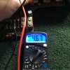
Embarrassingly I can’t find R25. I’m still looking.And R 25?
GrisPato
Super Member
Could be the bridge rectifier, (D601 & D602) but somewhat more likely to be Output Transistors - or damaged bias components causing OP transistors to run too much current.
I think Hyperion was close to the solution early on in the thread.
Do you have any KSC 1845?