I don’t know what you mean by ksc 1845, but we can replace D601 & 602 can’t we? The OP trans as you know have been replaced and that at least got our DBT to move.I think Hyperion was close to the solution early on in the thread.
Do you have any KSC 1845?


You are using an out of date browser. It may not display this or other websites correctly.
You should upgrade or use an alternative browser.
You should upgrade or use an alternative browser.
Barn find Sansui AU-7900
- Thread starter Kylek1443
- Start date
I’ll be able to check it in the morning ASAP.It is the one next to r23, closer to vR1

GrisPato
Super Member
This is the replacement transistor for the 2sc711 bias transistor.I don’t know what you mean by ksc 1845, but we can replace D601 & 602 can’t we? The OP trans as you know have been replaced and that at least got our DBT to move.
R25 measures .68 with the MM set to 20k ohms. How should I test TR05?And R 25?
At 2K ohms on the multi meter R25 measures .663And R 25?
GrisPato
Super Member
Resistors are good. Of course sometimes variable resistors can misbehave under power.
If you would have had a replacement for the bias transistor that would be the easy way to check by just replacing it.
We can find out more with some measurements but would have to happen with power on.
That will mean there is the risk of shorting something somewhere so you have to be reall careful.
I would like to see the voltage between r29( from one of the leads) to ground ( often chassis, but need a place with good contact). That from both channels ( r30 right channel) to compare. Prepare well so you can make contact with both points easily.
I don’t have a replacement on hand, but I can order one. This would be a replacement for TR05? Should I get 2 and replace both channels?Resistors are good. Of course sometimes variable resistors can misbehave under power.
If you would have had a replacement for the bias transistor that would be the easy way to check by just replacing it.
We can find out more with some measurements but would have to happen with power on.
That will mean there is the risk of shorting something somewhere so you have to be reall careful.
I would like to see the voltage between r29( from one of the leads) to ground ( often chassis, but need a place with good contact). That from both channels ( r30 right channel) to compare. Prepare well so you can make contact with both points easily.
It would be foolish to put the black lead of the MM on any metal part of the chassis? Is there a designated area?
Ill
I’ll have everything set up to test R29, R30 here in a bit. Power on. Black lead on ground and red lead of the MM on the resistor. What setting should the MM be on? 200m Volts?I have never seen this amplifier so don't know the internal configuration.
Sometimes an easily accessible place for ground reference can be the negative speaker terminal.
GrisPato
Super Member
@Hyperion
@Leestereo
Just a request to look into what I am trying to analyse.
I read up a little on the basic workings of a vbe multiplier circuit.
If I understand correctly multiplication is set by r23/(vR1+R25) so
minimum 4700/(470+680)=4.16*vbe
maximum 4700/680=6.91*vbe
What is the failure mode for the transistor to not being able to adjust bias below the ( now ) 260 mV. It looks to me as if the multiplication exceeds what normally should be possible with the resistors division.
Is it possible something in the circuit before the bias circuit upsets it making it impossible to function correctly?
Last edited:

Not well versed in the mathematics of this but TR05 has to turn on HARD to turn the bias down. The things that might prevent this is a faulty TR05 itself, OR out of spec resistors around it, including the trimmer VR01. If the bias is running too high then TR11 and TR13 are turned on too hard - if their bases are allowed to float towards the rails (voltage wise) high bias current will be the effect. But with TR05 in charge, 'turned on' and shorting the bases of TR11 & TR13 together that shouldn't happen.
OR there may be faulty components in the following parts of the circuitry, not so much TR07 & TR09 as these are concerned with overcurrent protection for the output transistors, and aren't usually a problem.
I hope this helps.
OR there may be faulty components in the following parts of the circuitry, not so much TR07 & TR09 as these are concerned with overcurrent protection for the output transistors, and aren't usually a problem.
I hope this helps.
Should we just go ahead and replace TR05?Not well versed in the mathematics of this but TR05 has to turn on HARD to turn the bias down. The things that might prevent this is a faulty TR05 itself, OR out of spec resistors around it, including the trimmer VR01. If the bias is running too high then TR11 and TR13 are turned on too hard - if their bases are allowed to float towards the rails (voltage wise) high bias current will be the effect. But with TR05 in charge, 'turned on' and shorting the bases of TR11 & TR13 together that shouldn't happen.
OR there may be faulty components in the following parts of the circuitry, not so much TR07 & TR09 as these are concerned with overcurrent protection for the output transistors, and aren't usually a problem.
I hope this helps.
How does this look to you?If you can find the ksc1845 it would be an option.
Attachments
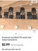
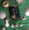
Hey Gris, I ordered those transistors for TR05. Waiting on them to come in. My question is, they are soldered, and bent through those cutouts on the pcb. The backs are (were originally) glued to the heatsink. Do they need to attach to the heatsink in order to work? Can they just be soldered in place and not bent? I have some pictures, hope you know what I mean.If you can find the ksc1845 it would be an option.
Attachments

GrisPato
Super Member
Transistors will work without touching the heatsink but they will track the temperature of the driver and outputs better if they do make good contact with the heatsink.Hey Gris, I ordered those transistors for TR05. Waiting on them to come in. My question is, they are soldered, and bent through those cutouts on the pcb. The backs are (were originally) glued to the heatsink. Do they need to attach to the heatsink in order to work? Can they just be soldered in place and not bent? I have some pictures, hope you know what I mean.
By the way, be aware that the ksc1845 transistors will probably have different pin out then the 2sc711. They both are with collector in the centre, but I think they have emitter and base swapped.
That will also mean you will not have the flat side facing the heatsink.
We're you able to do the voltage reading at the resistors r28-30?
Sorry for the delay in response. Had some stuff I had to take care of yesterday. I’ll try and get those voltage readings for you today.Transistors will work without touching the heatsink but they will track the temperature of the driver and outputs better if they do make good contact with the heatsink.
By the way, be aware that the ksc1845 transistors will probably have different pin out then the 2sc711. They both are with collector in the centre, but I think they have emitter and base swapped.
That will also mean you will not have the flat side facing the heatsink.
We're you able to do the voltage reading at the resistors r28-30?
GrisPato
Super Member
That are really weird readings.Ok I measured those resistors, power on, MM set to 200m. R-30 on the good channel measured 15.6V.
R29 on the bad channel measured a whopping 110.6V
I will be getting those new transistors for TR05 today in the mail.
Just to make sure,
Range of DMM: 20volt
Measured between one of the leads of r29 to ground and between one of the leads of r30 and ground.