How should I measure this voltage? Same way as the resistors? Black in ground and red on emitter?When you've made sure that all components you installed are correct I would be interested in the voltage at the emitter of tr19-21-23-25. So voltage between outside of emitter resistor to ground.


You are using an out of date browser. It may not display this or other websites correctly.
You should upgrade or use an alternative browser.
You should upgrade or use an alternative browser.
Barn find Sansui AU-7900
- Thread starter Kylek1443
- Start date
I need to locate TR 19-21-23-25 on the board. Looking now.When you've made sure that all components you installed are correct I would be interested in the voltage at the emitter of tr19-21-23-25. So voltage between outside of emitter resistor to ground.
R29 & R30? Sorry for sounding confused and ignorant :|They are the emitter resistors

GrisPato
Super Member

They are your output transistors on your left channel. There emitter resistor r59-61, r67-69, where you measured the bias voltage. That you did from one side of one resistor to the other side of the one next to it. Now I want from one side to the other side of one and then the other. So over one resistor and then the other one.
GrisPato
Super Member
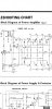
Imagen, Sansui even provided a diagram with the function and voltages to expect.
As you can see at r29,30 is to be expected a voltage of 1.9 V.
This we will have to clarify. Because you got 6-7 V there.
If only the bad channel would have had this it would have put my attention to upstream D01, tr01. But you have the same high voltage in the good channel to.
As you can see in the diagram the voltage drops around 0.6 V over each transistor so that you are left with around 10 mV on the outputs, which would cause the bias current for them.
You now have 260 mV on them in the left channel, which should be, if you measure 6.6 V at r29 more then 4.5 volt.
The only conclusion I can come to is that there is something amiss with your measurements.
Measuring R29, power on, MM set to 20V range, black lead in black speaker output, volume all the way down, set to AUX, it bounces around 6.30View attachment 2531604
Imagen, Sansui even provided a diagram with the function and voltages to expect.
As you can see at r29,30 is to be expected a voltage of 1.9 V.
This we will have to clarify. Because you got 6-7 V there.
If only the bad channel would have had this it would have put my attention to upstream D01, tr01. But you have the same high voltage in the good channel to.
As you can see in the diagram the voltage drops around 0.6 V over each transistor so that you are left with around 10 mV on the outputs, which would cause the bias current for them.
You now have 260 mV on them in the left channel, which should be, if you measure 6.6 V at r29 more then 4.5 volt.
The only conclusion I can come to is that there is something amiss with your measurements.
Attachments


Last edited:
R30 same connections measures over 7.40View attachment 2531604
Imagen, Sansui even provided a diagram with the function and voltages to expect.
As you can see at r29,30 is to be expected a voltage of 1.9 V.
This we will have to clarify. Because you got 6-7 V there.
If only the bad channel would have had this it would have put my attention to upstream D01, tr01. But you have the same high voltage in the good channel to.
As you can see in the diagram the voltage drops around 0.6 V over each transistor so that you are left with around 10 mV on the outputs, which would cause the bias current for them.
You now have 260 mV on them in the left channel, which should be, if you measure 6.6 V at r29 more then 4.5 volt.
The only conclusion I can come to is that there is something amiss with your measurements.
Attachments
Have a chance to measure things today and I think this was the other thing you wanted to know. Here soon I should have tr 19-21-23-25 measured for youWhen you've made sure that all components you installed are correct I would be interested in the voltage at the emitter of tr19-21-23-25. So voltage between outside of emitter resistor to ground.
Driver and outputs replaced with all new mica. NPN and PNP are correct. As with drivers too. I DID replace a cap on each channel. One cap in particular looked bulged out, it was a 50v 1uf that I replaced with a nichicon gold 50v 1uf. Could new caps cause it?Then, as I always do with everything I do myself in equipment, what did I touch and what could have gone wrong with that.
So driver and outputs are replaced.
Are all mica insulators good?
Pinouts, the TO-3 cases can just be installed one way. I think I checked placement of NPN and PNP but can check again. This also for the drivers.
My eyes aren’t that great but I’ve looked and looked and can’t find TR19,21,32,25 anywhere on the board. I know you said use the emitter resistors, but I’m not completely sure what you mean by that. Sorry for being confused. I feel like I’m not helping out very well.When you've made sure that all components you installed are correct I would be interested in the voltage at the emitter of tr19-21-23-25. So voltage between outside of emitter resistor to ground.

They are the large heatsink mounted Output transistors whose emitter resistors (the white blocks) are on the PCB next to the large heatsink.I’ve looked and looked and can’t find TR19,21,32,25 anywhere on the board

Hyperion! Glad to have you back! So the OP transistors are actually TR19,21,25,32? I’m still confused on how I should measure the emitter of them. Black to ground on the MM, set to 20V, and measure at the emitter resistors?They are the large heatsink mounted Output transistors whose emitter resistors (the white blocks) are on the PCB next to the large heatsink.
GrisPato
Super Member
Sorry for the confusion with the emitter and so forth.
I will explain what I am trying to achieve for now.
Because you are measuring 6-7 volt where there should be 1.9 volt and I don't want us chasing our tail I need some more values.
As you have shown, the method you used for these values was correct.
So there are two options:
You really have 6-7 volt there
Or, the ground reference is not correct. (Meaning, we assume this is 0.00 volt just in the middle of the positive and negative rail voltages.) If it's not we go chasing ...
Because when we measure the bias current ( in voltage over a resistor) we just measure the voltage over that two resistors, nothing more. So we don't know what the voltage difference is to ground.
The question is, measure the same way as you did the bias with the red lead on the inside leg of the resistor and black lead to ground
And repeat this with all four, R59,61,67,69.
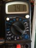
I think I measured the voltage on the emitters correctly this morning. It looks like all of them are measuring around 5.51-5.56 with the MM set to 20V range.View attachment 2531604
Imagen, Sansui even provided a diagram with the function and voltages to expect.
As you can see at r29,30 is to be expected a voltage of 1.9 V.
This we will have to clarify. Because you got 6-7 V there.
If only the bad channel would have had this it would have put my attention to upstream D01, tr01. But you have the same high voltage in the good channel to.
As you can see in the diagram the voltage drops around 0.6 V over each transistor so that you are left with around 10 mV on the outputs, which would cause the bias current for them.
You now have 260 mV on them in the left channel, which should be, if you measure 6.6 V at r29 more then 4.5 volt.
The only conclusion I can come to is that there is something amiss with your measurements.
GrisPato
Super Member
from the emitter to ground you get measurements of 5.5 volts!I think I measured the voltage on the emitters correctly this morning. It looks like all of them are measuring around 5.51-5.56 with the MM set to 20V range.
This is consistent for the right channel, 5.5 + 2 = the 7.5 you had at r30.
For the left channel we are 1 volt down.