I must not have done it correctly. I’ll try again on 20V. Red lead on a resistor and black on a ground.That are really weird readings.
Just to make sure,
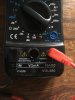
Range of DMM: 20volt
Measured between one of the leads of r29 to ground and between one of the leads of r30 and ground.


You are using an out of date browser. It may not display this or other websites correctly.
You should upgrade or use an alternative browser.
You should upgrade or use an alternative browser.
Barn find Sansui AU-7900
- Thread starter Kylek1443
- Start date
Ok redoing it hopefully correctly this time. MM on 20V, power on, black lead in negative speaker terminal, red lead on resistor. I got 7.49v on R-30 and 6.64V on R-29That are really weird readings.
Just to make sure,
Range of DMM: 20volt
Measured between one of the leads of r29 to ground and between one of the leads of r30 and ground.
Ahhh. Volume was at zero and source was on AUX but I was not on DC. I need to swap my red lead over to 10ADC. Let me try it again! Lol. Hopefully 3rd time is a charmAnd DMM on DC?
Doing it with the red lead swapped over to 10ADC doesn’t move the MM at all. It does dim the bulb and make it flash for a second though.And DMM on DC?
Attachments

GrisPato
Super Member
Sorry for confusing you. The leads.of the DMM were in the right place. Just wanted to make sure you had range on DC volt and not AC.
I can not make anything with the readings you got. From that resistor you will have three diode voltage drops (be) which would mean you would have around 5 volt left for the quiescent current ( bias )??
So I am trying to see what went wrong with the measurements.
I can not make anything with the readings you got. From that resistor you will have three diode voltage drops (be) which would mean you would have around 5 volt left for the quiescent current ( bias )??
So I am trying to see what went wrong with the measurements.
Measured the second time I was definitely on 20V DC (the blue side, pictured) The black lead was in a black negative speaker terminal. Power on, those were the readings it gave me. Perhaps my MM is junk?Sorry for confusing you. The leads.of the DMM were in the right place. Just wanted to make sure you had range on DC volt and not AC.
I can not make anything with the readings you got. From that resistor you will have three diode voltage drops (be) which would mean you would have around 5 volt left for the quiescent current ( bias )??
So I am trying to see what went wrong with the measurements.
Attachments
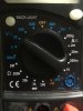
Just got those transistors in the mail. Should I go ahead and replace TR05? And while I’m at it should I replace the one on the other channel too or leave it alone? Waiting on your thoughts before I continue.10 ADC is for larger current measurement.
Attachments

Last edited:
Can we be 100% sure about this? I will absolutely swap them around. But I need to be 100% sure they go in backwards before I proceed.Transistors will work without touching the heatsink but they will track the temperature of the driver and outputs better if they do make good contact with the heatsink.
By the way, be aware that the ksc1845 transistors will probably have different pin out then the 2sc711. They both are with collector in the centre, but I think they have emitter and base swapped.
That will also mean you will not have the flat side facing the heatsink.
We're you able to do the voltage reading at the resistors r28-30?
Attachments


Ignore this post. I see what you mean now. Emitter and base. I got it
Attachments
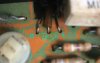
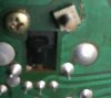

Installed the new transistor in TR05. VR01 won’t adjust at all. DBT dims then flashes, then stays lit. VR02 still adjusts to the correct bias. That channel seems fine.
Attachments

Last edited:
GrisPato
Super Member
Mhhh, I had a feeling already it wasn't tr05.
I am still stumped by the 6-7 volt readings you had on r29-30.
If I just forget that I was expecting around 2 volt and just compare the 2 channels then the lower voltage ( -0.850 V) in the left channel is caused by the excessive current.
So then something downstream is not functioning correctly.
I am still stumped by the 6-7 volt readings you had on r29-30.
If I just forget that I was expecting around 2 volt and just compare the 2 channels then the lower voltage ( -0.850 V) in the left channel is caused by the excessive current.
So then something downstream is not functioning correctly.
What could it be? There are only so many things downstream? I’m stumped as to what to do next. This thing has become a headache but i feel I’m either so close, or so far away.Mhhh, I had a feeling already it wasn't tr05.
I am still stumped by the 6-7 volt readings you had on r29-30.
If I just forget that I was expecting around 2 volt and just compare the 2 channels then the lower voltage ( -0.850 V) in the left channel is caused by the excessive current.
So then something downstream is not functioning correctly.
GrisPato
Super Member
Then, as I always do with everything I do myself in equipment, what did I touch and what could have gone wrong with that.
So driver and outputs are replaced.
Are all mica insulators good?
Pinouts, the TO-3 cases can just be installed one way. I think I checked placement of NPN and PNP but can check again. This also for the drivers.
So driver and outputs are replaced.
Are all mica insulators good?
Pinouts, the TO-3 cases can just be installed one way. I think I checked placement of NPN and PNP but can check again. This also for the drivers.
GrisPato
Super Member
PlentyThere are only so many things downstream