• The move to the new server is done. There are some software and database maintenance updates in process. This has us passing the hat around to help out. We appreciate any donations. Seriously, even a dollar helps. The payment page may be found here - https://www.audiokarma.org/support.html

Barn find Sansui AU-7900

Start here.
First you mention you measured four output transistors, there are eight, how are the other ones. You do not mention one of them is shorted, just measuring different, although this probably means it is faulty we don't know yet if this was causing the fuses to blow.
If none of your outputs is shorted and no resistors blew up it can be your driver transistors are good. Because they are really good transistors you just want to replace them when they are faulty. Replacement would be Onsemi mje15028/29-30/31.
Be sure to measure all transistors preferably out of circuit. Identify NPN and PNP types and record placement.

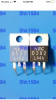
I mistyped. The 4 transistors B537/D382 were the ones I was talking about. The 8 transistors all seemed fine regardless of corrosion. My problem seems to be with the B537/D382 transistors and I’m looking for replacements. Two of each. Is there anything available that is the equivalent to those that aren’t found on eBay and China?
 

Attachments

  • BAC58831-CE8C-4F84-8BAF-C771912640BD.png
    BAC58831-CE8C-4F84-8BAF-C771912640BD.png
    430.4 KB · Views: 12
Start here.
First you mention you measured four output transistors, there are eight, how are the other ones. You do not mention one of them is shorted, just measuring different, although this probably means it is faulty we don't know yet if this was causing the fuses to blow.
If none of your outputs is shorted and no resistors blew up it can be your driver transistors are good. Because they are really good transistors you just want to replace them when they are faulty. Replacement would be Onsemi mje15028/29-30/31.
Be sure to measure all transistors preferably out of circuit. Identify NPN and PNP types and record placement.
that is what I want to replace next.
 

Attachments

  • 73C164BC-A6EE-4A12-AE9B-C4D050535EA8.jpeg
    73C164BC-A6EE-4A12-AE9B-C4D050535EA8.jpeg
    73.2 KB · Views: 28
  • 1BF1ACDA-75D1-410D-892F-547D5BA849BD.png
    1BF1ACDA-75D1-410D-892F-547D5BA849BD.png
    430.4 KB · Views: 25
Can be replaced with Onsemi mje15028/29 or 15030/31.
Which junction (bc, be, ce,cb,eb,ec) from which transistor (B537, D382, channel) measured what (voltage) different? Measured in circuit or out of?

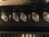
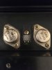
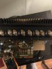
I measured them still in circuit. It’s the second D382 that measures well below the other 3 transistors. Pictured are the ones I was thinking of buying. Do you agree? Also pictured is the bad transistor. It would be the 3rd one from the end, the second black D382. Also can you tell me which is swapped with which? D382 swaps with 15028? And B537 swaps with 150829?
 

Attachments

  • 3BB564DE-09D9-4C61-809D-AAEEB190B297.jpeg
    3BB564DE-09D9-4C61-809D-AAEEB190B297.jpeg
    54.2 KB · Views: 35
  • image.jpg
    image.jpg
    71 KB · Views: 37
  • image.jpg
    image.jpg
    93.8 KB · Views: 35
2sb is PNP, 2sd is NPN.
Measuring diffent value on a transistor in circuit can also be caused by surrounding components but nothing wrong in replacing them.
I hope you realise you still have not found the short that blew up two 8 ampere fuses!!
 
2sb is PNP, 2sd is NPN.
Measuring diffent value on a transistor in circuit can also be caused by surrounding components but nothing wrong in replacing them.
I hope you realise you still have not found the short that blew up two 8 ampere fuses!!
isnt this where I should start though? Wouldn’t these transistors most likely be the cause of the short blowing the fuses? It’s likely not a cap, right? Just wondering what it could be.
 
Could be the bridge rectifier, (D601 & D602) but somewhat more likely to be Output Transistors - or damaged bias components causing OP transistors to run too much current. ;)
What’s you’re thoughts though? Where would you start? Replacing the D382/B537 transistors would be a good idea to start with, right? You guys have been an unbelievable help to me. I really do apologize if I ask dumb naive questions.
 
Ok, you can test those transistors (the drivers) to verify if they work - using the '6 way test' (with your multimeter), or one of those simple semiconductor testers if you have one, there is absolutely no need to replace them just because they are old. You also need to test the OP transistors in the same way, with many multimeters they'll test at between around 500 & 600 on the meter (set to diode test range). Obviously(?) NPN transistors if good, will show an opposite set of readings to a PNP transistor, anything higher or lower indicates a problem with that transistor and 'it' and its opposite number, as you show above, should be discarded and replaced together.

If you are wrong about any of the devices and re-install them in the amplifier - the way to prevent them, or others getting damaged when you apply power is to use a DBT, or Dim Bulb Tester. This just puts an incandescent bulb filament (60W for an AU-7900), in series with the mains transformer primary winding which limits current, and nearly always prevents damage caused by incorrectly orientated or damaged components - PROVIDING you power off immediately you see a bright bulb for more than 2 or 3 seconds, if the bulb is 'full bright' turn off immediately, but in either case check your work! What you should see is a bright bulb for a couple of seconds which then rapidly dims away to almost nothing, this is a good indication that things are probably OK (not definitely, but probably).

Your suspected short circuit, taking out 8A fuses.
To test for this short take out both 8A fuses and disconnect pins 18 and 19 on the F-2596 board. you can then test the rectifiers looking for short circuits using your multimeter, if you find none then reconnect 18 & 19 (this is the feed to the main PSU capacitors) and disconnect 20 & 21 (this is the feed from the PSU capacitors to the amp board). You can test this by re-inserting the 8A fuses and powering up via a DBT and measuring the voltage at pins 18 & 19 to chassis ground.

I'll leave it there for you to understand and ask questions about... ;)
 
Ok, you can test those transistors (the drivers) to verify if they work - using the '6 way test' (with your multimeter), or one of those simple semiconductor testers if you have one, there is absolutely no need to replace them just because they are old. You also need to test the OP transistors in the same way, with many multimeters they'll test at between around 500 & 600 on the meter (set to diode test range). Obviously(?) NPN transistors if good, will show an opposite set of readings to a PNP transistor, anything higher or lower indicates a problem with that transistor and 'it' and its opposite number, as you show above, should be discarded and replaced together.

If you are wrong about any of the devices and re-install them in the amplifier - the way to prevent them, or others getting damaged when you apply power is to use a DBT, or Dim Bulb Tester. This just puts an incandescent bulb filament (60W for an AU-7900), in series with the mains transformer primary winding which limits current, and nearly always prevents damage caused by incorrectly orientated or damaged components - PROVIDING you power off immediately you see a bright bulb for more than 2 or 3 seconds, if the bulb is 'full bright' turn off immediately, but in either case check your work! What you should see is a bright bulb for a couple of seconds which then rapidly dims away to almost nothing, this is a good indication that things are probably OK (not definitely, but probably).

Your suspected short circuit, taking out 8A fuses.
To test for this short take out both 8A fuses and disconnect pins 18 and 19 on the F-2596 board. you can then test the rectifiers looking for short circuits using your multimeter, if you find none then reconnect 18 & 19 (this is the feed to the main PSU capacitors) and disconnect 20 & 21 (this is the feed from the PSU capacitors to the amp board). You can test this by re-inserting the 8A fuses and powering up via a DBT and measuring the voltage at pins 18 & 19 to chassis ground.

I'll leave it there for you to understand and ask questions about... ;)

Going over your reply. Trust me I’ll go over your reply multiple times. But my first response is that a DBT costs $60 to buy one and building one isn’t really an option. I’m doing this project for a friend and really don’t want to spend a ton on it. So honestly a DBT is far fetched for me to buy just for this project. I understand that it can be multiple things going wrong to blow these fuses, but I have to start some where. I originally started with the fuse resistors. Had the same outcome of blowing the fuses. My next lead was to the transistors. With my minimal experience in these amps, my only thought is to replace one piece at a time until I finally find the fault. Again I appreciate more than you can imagine the help you guys have given me. But please, talk to me like I’m a 5 years old . I doubt it’s the rectifier bridge, I doubt that it’s the filter caps. I feel, and feel is a strong word, but I feel that the fault is the amp board, specifically the transistors. Still feel I’m not expressing the problem/understand things I’m told on here. Again, thank you guys for working with me.
 
Last edited:
This is my dim bulb tester!

1646087247321216668712176424516.jpg

Two sockets in series. I plug in a lamp wit switch in one, the amplifier in the other. I only use it for testing for a short and maybe some first voltage measurement of the powersupply. Maximum 5 minutes. Some people use it for more testing, etc and than it can be useful to have a more elaborate design but this is all you need.
About the short. Ofcourse the most common reason is blown outputs but sometimes it's not.
My experience is more with computer motherboards and game consoles.
This is indeed something completely different, you have in a way modules you can swap, this is discrete design, the risk with starting to shotgun components is mostly that you are in the end introducing more variables that can be of.
Follow Hyperion advice and you will get to somewhere.
 
If you or the owner are not willing to invest in a dim bulb tester, I don't think you should be messing with the amplifier. It is the first testing and test equipment in the troubleshooting process. If you are fearless about working on an amplifier, then why is building a dim bulb tester not a possibility?
A DBT consists in its basic form 1). A mains power cord 2). A standard receptacle 3). A lamp socket for a standard screw-in incandescent bulb, and as mentioned 4). A 60 watt incandescent bulb.
The power cord and receptacle can be the male and female ends of a dollar store extension cord, which would also provide any hookup wire needed.
The lamp socket should cost a few dollars at a Home Depot store or at a Walmart. Or scrounged from an unused lamp.
Without employing the protection a DBT affords, I can picture the new and possibly original amplifier components blowing up time after time.
 
Last edited:
This is my dim bulb tester!

View attachment 2499141

Two sockets in series. I plug in a lamp wit switch in one, the amplifier in the other. I only use it for testing for a short and maybe some first voltage measurement of the powersupply. Maximum 5 minutes. Some people use it for more testing, etc and than it can be useful to have a more elaborate design but this is all you need.
About the short. Ofcourse the most common reason is blown outputs but sometimes it's not.

This is indeed something completely different, you have in a way modules you can swap, this is discrete design, the risk with starting to shotgun components is mostly that you are in the end introducing more variables that can be of.
Follow Hyperion advice and you will get to somewhere.
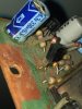
Just an update: Building my DBT within the next few days. I also was wondering if you would know a good replacement for this transistor. It’s at spot TR603 on the amplifier board. Transistor says C1364 676 on it. The leads are encrusted with black like it might have been damaged. None of the others near it have that black on it.
 

Attachments

  • image.jpg
    image.jpg
    110.9 KB · Views: 34
Original fit normally used '2SC945' = KSC945CYTA
https://www.mouser.co.uk/ProductDetail/onsemi-Fairchild/KSC945CYTA?qs=ljbEvF4DwOOXrfZIdV33Ew==

'C1364' 676 - this means 2SC1364 and '676' means datecode/batch number (ignore)

;)
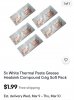
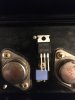
Thank you so much. Have another one for you when you get the chance. Would you trust this thermal paste for those transistors on the heatsink? I purchased these transistors (pictured) and was wondering about this paste (pictured). I have tons of silver cpu paste but I’ve heard that’s a big no no for this application. Thanks again!
 

Attachments

  • FEB5A762-8806-4436-86AA-78CDBFAE6B70.jpeg
    FEB5A762-8806-4436-86AA-78CDBFAE6B70.jpeg
    54.2 KB · Views: 20
  • E18D0593-7795-413B-A33E-9AE8F551C4E0.jpeg
    E18D0593-7795-413B-A33E-9AE8F551C4E0.jpeg
    102.9 KB · Views: 19
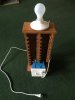
Built my DBT today. Had a blast. Thought you guys might get a kick out of it. That old cassette holder came in handy! Hope I did everything correctly. Either way it was a fun build!
 

Attachments

  • 6429A241-889C-4595-AB0A-47DC01CA6AC1.jpeg
    6429A241-889C-4595-AB0A-47DC01CA6AC1.jpeg
    120 KB · Views: 60
Built my DBT today. Had a blast. Thought you guys might get a kick out of it. That old cassette holder came in handy! Hope I did everything correctly. Either way it was a fun build!
Well done. This tool although simple can help you a lot. It can give some information about severity of a short and at least give you a chance to test after replacing the drivers for a short without breaking something right away again. There is also a small possibility that your main filter capacitors haven't seen any voltage in a long time and can recover a little with the lower voltage provided through the DBT. I have to say, the fact that your output transistors have no shorts, gives me a feeling it could be your bridge rectifier. Even the fact they don't fail often doesn't mean they never fail.
Keep us updated
 
Hey guys! Got parts in. Have my DBT ready. Before I start I need to check with everyone to make sure these are correct. Are these the transistors in the correct order? D382 replaced with 28G and R537 replaced with 29G? I just want to make sure I have the correct order.
 

Attachments

  • C6DF844D-8729-4475-A172-5C77039A3B6D.jpeg
    C6DF844D-8729-4475-A172-5C77039A3B6D.jpeg
    57.3 KB · Views: 35
  • 831FADF9-4517-409E-9638-E750AEC275F4.jpeg
    831FADF9-4517-409E-9638-E750AEC275F4.jpeg
    72 KB · Views: 33
Back
Top Bottom