

You are using an out of date browser. It may not display this or other websites correctly.
You should upgrade or use an alternative browser.
You should upgrade or use an alternative browser.
Barn find Sansui AU-7900
- Thread starter Kylek1443
- Start date
I’ll go over your response a few times before I’m able to give you the full answer, but to start, the DBT did not dim. It is lit as bright as can be constantly.Did the bulb go dim at this occasion? Just to be sure.
About replacing rectifier diodes, filter capacitors. Sure you can do this but you wouldn't be the first one that is left with the same problem.
I would advice you to test the rectifier diodes for shorts. This means you localise where one starts and where it ends. Put the DMM in diodetest and measure both ways. You will have to do that four times. Test also the mica insulators from the outputs. One lead on the case one on the heatsink. Make sure you make good contact and measure resistance, should be OL.
Eight times ofcourse.
Otherwise you replaced a lot of components to find out it was something really simple.

GrisPato
Super Member
Take your time. You mentioned learning curve before, consider this a steep one.I’ll go over your response a few times before I’m able to give you the full answer
Most important you have to think about is that you are looking for a shorted circuit. So even just with an Ohms meter you can find that
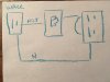
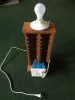
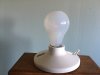
Here is an extremely crude drawing it did of how I wired it. Hot from the wall outlet goes strait to the “ON” on my switch. The “OFF” of the switch goes to the neutral of the outlet on my DBT, through a jumper wire. I broke the connection on the socket from neutral to neutral and left the other side of the socket “hot” intact. I then ran my neutral directly from the wall to the neural of the socket on the DBT. I have a plug connected to the light bulb and plug that into the DBT socket. Then plug in my amp.
Attachments
GrisPato
Super Member
Good, that is in series.
Bad, getting worried about the transformer a little.
If you take all the fuses out and put it on with DBT in between the light should go dim.
When that happens you go one step further. Put the 8 A fuses back in, preferably with wires to point 20-21 on driverboard disconnected, and try again with the DBT.
Bad, getting worried about the transformer a little.
If you take all the fuses out and put it on with DBT in between the light should go dim.
When that happens you go one step further. Put the 8 A fuses back in, preferably with wires to point 20-21 on driverboard disconnected, and try again with the DBT.
With all 4 fuses in the power indicator light comes on and the bulb on the DBT lights up bright.Good, that is in series.
Bad, getting worried about the transformer a little.
If you take all the fuses out and put it on with DBT in between the light should go dim.
When that happens you go one step further. Put the 8 A fuses back in, preferably with wires to point 20-21 on driverboard disconnected, and try again with the DBT.
removing any of the two sets of fuses, OR removing all 4 fuses, the DBT doesn’t light at all and the power indicator light on the Sansui does not light.
removing cords 20 and 21 and leaving all fuses in the DBT lights and dims.
so we have DBT dimming when 20 and 21 removed. …. Is it bad fellas?
Good, that is in series.
Bad, getting worried about the transformer a little.
If you take all the fuses out and put it on with DBT in between the light should go dim.
When that happens you go one step further. Put the 8 A fuses back in, preferably with wires to point 20-21 on driverboard disconnected, and try again with the DBT.
Attachments

No that's good! - it suggests that the transformer, the main rectifiers and the main filter capacitors are not faulty.so we have DBT dimming when 20 and 21 removed. …. Is it bad fellas?

But it begins to suggest that the Output Transistors are suspect - either because they are being turned on too hard (due to faulty 'driver' or other transistors), or because they are shorted.
No that's good! - it suggests that the transformer, the main rectifiers and the main filter capacitors are not faulty.
But it begins to suggest that the Output Transistors are suspect.
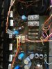
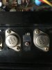
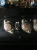
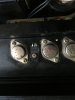
those would be the 8 silver ones? I replaced the 4 in between them. What’s my next step? (Side note thank you so much I can’t begin to tell you my gratitude. I feel so ignorant asking you such rookie level questions.).
Attachments

Other than replacing the 220ohm fuse resistors, and replacing those 4 transistors on the heatsink, I haven’t touched the board. I know we need to repair before we restore. But I got ahead of myself.No that's good! - it suggests that the transformer, the main rectifiers and the main filter capacitors are not faulty.
But it begins to suggest that the Output Transistors are suspect - either because they are being turned on too hard (due to faulty 'driver' or other transistors), or because they are shorted.
20,21 removed and the DBT brights and dims instantly. Power indicator light comes on.
when 20,21 connected, and all fuses in, DBT lights up bright.
When plugged strait into a wall, BOTH 8A 250V on Sansui F-2596 blow instantly when amp turns on.
(Just refreshing everyone, I know everyone commenting knows thus far)
Attachments
-
 16B7501E-7047-4AB0-91BC-E5287D4DFC1F.jpeg82.7 KB · Views: 23
 -
 F30553DA-DC47-45E0-A872-8B750C92BDDD.jpeg79.3 KB · Views: 24
 -
 6EEC4BEA-A685-47F1-8AB9-AC150CF829D9.jpeg78.3 KB · Views: 22
 -
 2A9E88C9-5C44-4C34-AFE2-17904A4433AC.jpeg77.9 KB · Views: 22
 -
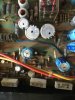 24C9760C-1071-4018-A989-C5036A473676.jpeg117.8 KB · Views: 21
 -
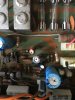 D4D7487D-70AF-45B6-B7B5-E5FA1D8E2A11.jpeg114.2 KB · Views: 21
 -
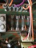 FD3374B2-2D9F-46EC-9100-150DAAE6C374.jpeg110.8 KB · Views: 22
 -
 3F3AA2C5-9FF8-4CD3-AF2B-89A94B26F22B.jpeg113.3 KB · Views: 21
How did you know which transistors went where? - there are 2 distinct types of transistor 2 of one type, and 2 of the other type - these are TR15 and TR17, (one of each type) and TR16 and TR18 (one of each type) - from your pictures I can't read the type numbers of the transistors - side lighting puts the transistors in shadow, and heatsink compound on the body of the transistors doesn't help.and replacing those 4 transistors on the heatsink,

Can you clean them up and give a better picture (with the text the right way up!) of the 4 of the transistors you replaced - with a view of them so I can see which ones are where??
Last edited:
GrisPato
Super Member
As Hyperion says, now we are going somewhere. This process always start with excluding parts of the circuit so you know where to concentrate your attention. To me best cause of action is to take the output transistors off the heatsink and test them. Before that would be smart to test the working of the mica isolation pads just to be sure they are not the cause. You can test the transistors better out of circuit so perform the six-way test. If that doesn't give any strange readings I guess you have to go looking at the bias network.
So important now: assume nothing! Collect data and act accordingly!
So important now: assume nothing! Collect data and act accordingly!
I replaced the two black NEC D382 L6YC with MJE15028G CQ218 & replaced the two blue NEC R537 L6YC with MJE15029G CQ235How did you know which transistors went where? - there are 2 distinct types of transistor 2 of one type, and 2 of the other type - these are TR15 and TR17, (one of each type) and TR16 and TR18 (one of each type) - from your pictures I can't read the type numbers of the transistors - side lighting puts the transistors in shadow, and heatsink compound on the body of the transistors doesn't help.
Can you clean them up and give a better picture (with the text the right way up!) of the 4 of the transistors you replaced - with a view of them so I can see which ones are where??
Attachments
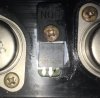
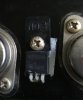

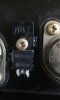
OK - thank you - that is correct. Those black tabs under the screws for those 4 transistors what are they made of? - if it's plastic then I think you won't have the collectors for those transistors connected to the PCB, - because connection is through the screw!
While you are thinking about that you can remove each of the 8 power transistors in turn (to avoid muddling them up), and test each of them. Don't bother to re-install faulty ones, but note where they came from.
This might help
https://audiokarma.org/forums/index...-transistor-testing-basics.43186/#post-432830
While you are thinking about that you can remove each of the 8 power transistors in turn (to avoid muddling them up), and test each of them. Don't bother to re-install faulty ones, but note where they came from.
This might help
https://audiokarma.org/forums/index...-transistor-testing-basics.43186/#post-432830
Last edited:
Those black things are made of plastic and there is a metal ring inside them in the hole the screw goes trough. I put everything back together the way I took it apart. I just put a small dot of thermal paste and spread it around the back of each transistor. I then put the clear plastic tab down on the heat sink and laid the transistor down, to be screwed in after I solders the leads into the board.OK - thank you - that is correct. Those black tabs under the screws for those 4 transistors what are they made of? - if it's plastic then I think you won't have the collectors for those transistors connected to the PCB, - because connection is through the screw!
While you are thinking about that you can remove each of the 8 power transistors in turn (to avoid muddling them up), and test each of them. Don't bother to re-install faulty ones, but note where they came from.
This might help
https://audiokarma.org/forums/index...-transistor-testing-basics.43186/#post-432830
I think we have looked before but could you possibly tell me what a good replacement pair for these would be? There’s stuff from China on eBay.. but .. I know that’s not what I should do. We should just replace them all.OK - thank you - that is correct. Those black tabs under the screws for those 4 transistors what are they made of? - if it's plastic then I think you won't have the collectors for those transistors connected to the PCB, - because connection is through the screw!
While you are thinking about that you can remove each of the 8 power transistors in turn (to avoid muddling them up), and test each of them. Don't bother to re-install faulty ones, but note where they came from.
This might help
https://audiokarma.org/forums/index...-transistor-testing-basics.43186/#post-432830
Attachments

GrisPato
Super Member
Don't buy old transistors from eBay. They are mostly fake Chinese except from very few US sellers. You can replace the output transistors with MJ21193/MJ21194G pair and for the driver transistors, you can use MJE15030/MJE15031 pair. You can buy them from a reputed source like Mouser or DigiKey.