Hey Gris sorry I didn’t get back with you yesterday. We’ve been having rolling blackouts in my part of the country and didn’t have power all afternoon and last night. Luckily I was able to measure those this morning. Between leads they all measure 00.3 at 200k on the MM. i assume that’s good? Next step is making sure I’m putting the leads in the correct holes on the board. I believe it goes like this. 3 at the top, 1 at the bottom, and 2 to the side. What do you think?Ohms measurements from lead 1 to 3, etc, range on DMM 2k


You are using an out of date browser. It may not display this or other websites correctly.
You should upgrade or use an alternative browser.
You should upgrade or use an alternative browser.
Barn find Sansui AU-7900
- Thread starter Kylek1443
- Start date
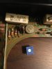
I’m honestly terrified of putting these in the wrong way.Ohms measurements from lead 1 to 3, etc, range on DMM 2k

GrisPato
Super Member

Here you see vR1, you see that they have the same drawing, just the arrow pointing the other way, so 1 and 3 where the resistor symbol is and 2 where the arrow points from/at.
Measure the trimmers range 2k between 1 and 3, should be 500 ohm or less depending on the position of the potentiometer. Check if it changes by turning.
Attachments
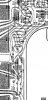
Ok Gris! Here’s where I’m at and I’m just lost. I pulled VR01. On the board it’s clearly marked with an arrow and the zig zag line. The part has the same symbol, between leads 1 and 3. The issue is that the leads don’t line up with the board. The leads and board are reversed. Hope you can tell what I mean from my pictures.Ohms measurements from lead 1 to 3, etc, range on DMM 2k
Attachments

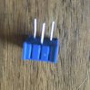

Does this look correct? I haven’t soldered in yet.View attachment 2614109
Here you see vR1, you see that they have the same drawing, just the arrow pointing the other way, so 1 and 3 where the resistor symbol is and 2 where the arrow points from/at.
Measure the trimmers range 2k between 1 and 3, should be 500 ohm or less depending on the position of the potentiometer. Check if it changes by turning.
Attachments
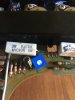
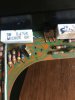
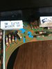
Ok great! I think I have it the right way. VR02 will go in the exact same way correct? 2,3 share a solder pad and the holes on VR02 are the same as the picture you just sent me?Ah, now I understand why the arrow points backwards, it points to lead 2.
View attachment 2614132
This is how it should go in.
Attachments

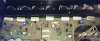
Got them both installed. I installed them in the exact same orientation. Putting everything back together now and plugging it into the DBT. I will not flip the switch until you are satisfied with the install. I want to be 100% sure everything is correct. Solder joints look great, and I’ve turned the dials fully counter clockwise.So lead 2 and 3 are going to share the same solderpad.
Attachments
GrisPato
Super Member
Yeah, let's try that. Keep your finger on the switch, if the bulb doesn't go dim in 2-4 seconds switch it of. ( I do think you're going to be ok)
When the bulb does go dim measure the bias voltage over the emitter resistors ( the white cement blocks), see if it moves by turning the trimmers. When it does dial them in at half of the bias voltage, so around 10 mV max.
Then you can take it of DBT and dial them in to required 18 mV.
Be sure to use the correct setting on the DMM!
Oh, and watch for increase in temperature or smoke the first few minutes mains voltage!!
Always be watchful!
When the bulb does go dim measure the bias voltage over the emitter resistors ( the white cement blocks), see if it moves by turning the trimmers. When it does dial them in at half of the bias voltage, so around 10 mV max.
Then you can take it of DBT and dial them in to required 18 mV.
Be sure to use the correct setting on the DMM!
Oh, and watch for increase in temperature or smoke the first few minutes mains voltage!!
Always be watchful!
Ok here we go. Just be clear the MM should be on 200DC when adjusting the bias, correct?Yeah, let's try that. Keep your finger on the switch, if the bulb doesn't go dim in 2-4 seconds switch it of. ( I do think you're going to be ok)
When the bulb does go dim measure the bias voltage over the emitter resistors ( the white cement blocks), see if it moves by turning the trimmers. When it does dial them in at half of the bias voltage, so around 10 mV max.
Then you can take it of DBT and dial them in to required 18 mV.
Be sure to use the correct setting on the DMM!
Oh, and watch for increase in temperature or smoke the first few minutes mains voltage!!
Always be watchful!
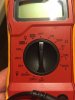
Ok yes mine goes lowest at 200m. Or is 2000m the lowestNo the lowest range on the DMM for volt DC. It think is 2000 ( 2V or 2000 mV)
Attachments
GrisPato
Super Member
200m, remember, you want to dial in to 10 mV first then to 18 mV!Ok yes mine goes lowest at 200m. Or is 2000m the lowest
Ok turned it on the DBT for the first time. Bad news. It’s flashing. Bright then dim then bright. No relay. I turned it off after 3 seconds of that.200m, remember, you want to dial in to 10 mV first then to 18 mV!
wait… ok. Cancel that. I turned both pods fully clockwise. Dim bulb and relay click on
Still having trouble with VR01. It will adjust somewhat but the numbers bounce all over the place. VR02 adjusts but as I turn the dial it goes into the negative numbers.200m, remember, you want to dial in to 10 mV first then to 18 mV!
GrisPato
Super Member
Bouncing how much?numbers bounce all over the place. VR02 adjusts but as I turn the dial it goes into the negative numbers.
" Into negative numbers" is this from positive numbers or from 0 to negative. The first would be really weird, the second is ok, just change out the leads of the DMM.