• The move to the new server is done. There are some software and database maintenance updates in process. This has us passing the hat around to help out. We appreciate any donations. Seriously, even a dollar helps. The payment page may be found here - https://www.audiokarma.org/support.html

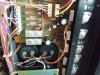
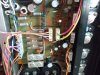
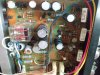
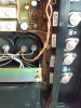
Barn find Sansui AU-7900

Bouncing how much?
" Into negative numbers" is this from positive numbers or from 0 to negative. The first would be really weird, the second is ok, just change out the leads of the DMM.
Now VR01 won’t adjust at all or really register anything.
VR02 when I try to adjust, and I say goes into the negative, looks like the picture shown. Sorry it’s kind of hard to see. But getting to 10 it’s got a negative symbol.
 

Attachments

  • C55538BC-7042-4E67-8025-63FF45D72EBD.jpeg
    C55538BC-7042-4E67-8025-63FF45D72EBD.jpeg
    63 KB · Views: 9
The negative is ok. If you change the leads of your DMM around it will be positive. Voltage is just a potential difference which we measure to a reference. If you go stand on something 10 meter high the ground is -10 m from you referenced to where you are.
If you stand on the ground the top of the building is + 10 meter from you referenced to the ground.
The black lead is determining your reference position!
 
The negative is ok. If you change the leads of your DMM around it will be positive. Voltage is just a potential difference which we measure to a reference. If you go stand on something 10 meter high the ground is -10 m from you referenced to where you are.
If you stand on the ground the top of the building is + 10 meter from you referenced to the ground.
The black lead is determining your reference position!
Ok great! So it sounds like VR02 is ok and passing the test. Our troubles are still now VR01 and figuring out why it’s behaving the way it is. We now know it’s not VR01 itself. Most every component around it has been changed. We have a DBT that dims and the relay clicks on. I’m at a loss honestly. What do you think?
 
Ok, so it wasn't the vR. Before changing more components we have to be absolutely sure about some things.
First: driver and outputs on the leftchannel do not leak current to the heatsink! Test with power of (always on resistance measurements).
From the collector of the transistors (metal cover on the TO3, metal tab in the TO220) range of DMM on 200K or higher, to the heatsink. Should be high reading or 0. Compare.with right channel.
Second: check orientation of the bias transistor tr05 and the solderjoints of it.
The bouncing of the readings on the leftchannel bias, were they in to the volts ( 1-2 volts), 100 mV, or just mV ( 1-20mV)?
 
Ok, so it wasn't the vR. Before changing more components we have to be absolutely sure about some things.
First: driver and outputs on the leftchannel do not leak current to the heatsink! Test with power of (always on resistance measurements).
From the collector of the transistors (metal cover on the TO3, metal tab in the TO220) range of DMM on 200K or higher, to the heatsink. Should be high reading or 0. Compare.with right channel.
Second: check orientation of the bias transistor tr05 and the solderjoints of it.
The bouncing of the readings on the leftchannel bias, were they in to the volts ( 1-2 volts), 100 mV, or just mV ( 1-20mV)?
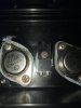
At every resistance setting on the MM, T03 case to heatsink all measured zero. Never got any reading. The metal tab on the other transistors has a plastic cover over it. Checking TR05 now. The bouncing when it happened on VR01, hasn’t happened since, Was going from 10-40v all in between. All power and output transistors have been replaced. I’m fairly sure nothing is touching.
 

Attachments

  • image.jpg
    image.jpg
    95.6 KB · Views: 7
This should be mV if you had the range of the DMM on 200m?
I turned it on this morning and let it sit on the DBT for about 5 minutes or so. Tested the bias for VR01 and still get nothing. Stays at 0 regardless of where I turn the dial. VR02 is working just fine.
 
check orientation of the bias transistor tr05 and the solderjoints of it.
Did you do this!
Also check al solderjoints of the leftchannel transistors starting at Tr11, 13 Al the way through to tr25.
If this is al ok then measure all resistors, from R43-49. All with power of.
If the bias voltage was fluctuating from 10-40 mV something is intermittent.
 
Just watching....
Many times I've had this problem, it usually turns out to be a solder bridge or a transistor that's replaced but backward . Check your work.
Edit: this applies to the 0mv problem. The fluctuation issue is interesting? o_O
I'll stand back and cheer!! Good luck
 
Did you do this!
Also check al solderjoints of the leftchannel transistors starting at Tr11, 13 Al the way through to tr25.
If this is al ok then measure all resistors, from R43-49. All with power of.
If the bias voltage was fluctuating from 10-40 mV something is intermittent.
Ok, so I went over the entire board looking for any irregularities or things that I didn’t already know about (having to creat new leads from point to point). The biggest problem with this board is every time a part is pulled the copper lead of the board pulls up and becomes loose. I’ve checked everything and can’t find a spot that i don’t think is connected. As for the fluctuation of VR01. That happened once and only once on the very first test after installing it. I’ve moved VR02 all the way down and have been able retested/turn it back to 10mv multiple times now. VR01 has constantly been at 0.00 and won’t budge.
 
The biggest problem with this board is every time a part is pulled the copper lead of the board pulls up and becomes loose. I’ve checked everything
This is my worry, that somewhere you loose connection. So you will have to Ohm through ( continuety) all connections starting from the bias network all the way to the outputs.
I guess there is 95% chance it is related to this.
 
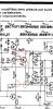
Before changing the trimpot you had max voltage of 600-700 mV. This would indicate a problem around tr05 ( vbe multiplier) because it's around one vbe (voltage over the diode junction base to emitter) and it should multiplying this when the voltage divider ratio changes with turning the trimpot. So check that out rigorously!

Screenshot_20220713-184523_Moon+ Reader.jpg

Screenshot_20220713-184918_Moon+ Reader.jpg
 
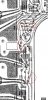
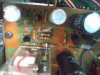
check them death diodes(little red ball with a bit of black or white) or just replace them- vd1212(3) with (2)1n4148 in series- black lines in same direction oriented as vd1212. add a glob of solder to the area and pull the component from the other side. clear the hole by applying iron then blowing or use a tooth pick. refer to pics for proper component orientation. :lurk:
 

Attachments

  • IMG_20220713_153713190.jpg
    IMG_20220713_153713190.jpg
    87.6 KB · Views: 17
  • IMG_20220713_153759971.jpg
    IMG_20220713_153759971.jpg
    80.9 KB · Views: 15
  • IMG_20220713_155744938.jpg
    IMG_20220713_155744938.jpg
    120.5 KB · Views: 16
  • IMG_20220713_155737863.jpg
    IMG_20220713_155737863.jpg
    122.2 KB · Views: 13
  • IMG_20220713_155730383.jpg
    IMG_20220713_155730383.jpg
    115.4 KB · Views: 16
  • IMG_20220713_155805271.jpg
    IMG_20220713_155805271.jpg
    108.6 KB · Views: 16
check them death diodes(little red ball with a bit of black or white) or just replace them- vd1212(3) with (2)1n4148 in series- black lines in same direction oriented as vd1212. add a glob of solder to the area and pull the component from the other side. clear the hole by applying iron then blowing or use a tooth pick. refer to pics for proper component orientation. :lurk:
Thank you for the tip. They are fairly cheap. How does this look to you?
 

Attachments

  • D429A379-B133-4902-9C1E-466A62CA3106.jpeg
    D429A379-B133-4902-9C1E-466A62CA3106.jpeg
    75.1 KB · Views: 13
Before changing the trimpot you had max voltage of 600-700 mV. This would indicate a problem around tr05 ( vbe multiplier) because it's around one vbe (voltage over the diode junction base to emitter) and it should multiplying this when the voltage divider ratio changes with turning the trimpot. So check that out rigorously!

View attachment 2614903

View attachment 2614917
TR05 Has been replaced. Everything on it looks to be ok as far as the joints.
 
This is my worry, that somewhere you loose connection. So you will have to Ohm through ( continuety) all connections starting from the bias network all the way to the outputs.
I guess there is 95% chance it is related to this.
I had to take a step away from it for a day. I’ve looked over the entire solder side of the board and while there are broken leads that have been prepared and yes the board is just a mess, I can’t find anything that isn’t connected. I’m honestly at a loss. I don’t think I’m capable of going through the entire circuit on my own.
 
Back
Top Bottom