• The move to the new server is done. There are some software and database maintenance updates in process. This has us passing the hat around to help out. We appreciate any donations. Seriously, even a dollar helps. The payment page may be found here - https://www.audiokarma.org/support.html

Beginning my Sansui AU-919 restoration

richiem46

Retired and enjoying life and music!
Subscriber
I restored a Sansui AU-717 last year for another AK'r and was very impressed with the sound quality of the finished unit. I documented this restoration in the thread below:


In April of last year I obtained an AU-919 from a different fellow AK'r for restoration. I left the AU-919 in Florida as we summer in Michigan and there was no sense starting the restoration as I knew, based on my experience with the AU-717 it would be an involved process.

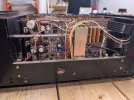
The AU-919 I received is remarkably clean, probably one of the cleanest units of any type I have serviced. All of the original Sansui output transistors are present which is great, hoping they are intact which will be the first thing I will determine. The AU-919 powers up but does not come out of protection. I have read a lot of threads on the restoration of the AU-919 and will plan my approach based on a summation of what I have read. One suggestion that makes sense is to replace the original Sansui NMC1012/NMA1012 output transistors and install sacrificial MJ21193G/MJ21194G transistors. That idea seens sensible....

I purchased a restoration kit from Peace-Love and Music as a parts base for my reatoration. I will probably re-stuff the four oval main filter caps as the kit contains the parts and some of the videos available are very helpful.

I welcome any and all suggestions as I begin my AU-919 project.
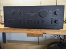

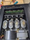
PXL_20251104_210143217.jpg

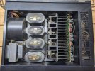
PXL_20251104_210153726.jpg
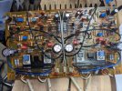
PXL_20251105_131541334.jpg

Buldging capacitors?

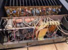
PXL_20251105_131553515.jpg

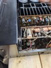
PXL_20251105_132053149.jpg

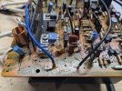
Some capacitor corrision visible above.....
PXL_20251105_132253771.jpg

PXL_20251105_132836125.jpg
 

Attachments

  • PXL_20251105_133236712.jpg
    PXL_20251105_133236712.jpg
    107.8 KB · Views: 11
  • PXL_20251105_132034235.jpg
    PXL_20251105_132034235.jpg
    137.1 KB · Views: 12
Register to hide this ad
Buldging capacitors?
No, they all do that - it's only the printed insert that distorts with heat.
Some capacitor corrision visible above.....
Yes, and there is very likely lots more - note that the Equaliser Amp (Phono) F-2835, is usually the worst affected by the glue, closely followed by the Power Amp Power Supply Board, F-2845, only second because there are fewer components needing to be removed to properly clean the glue. :rolleyes:

There are a few informative AU-919 restoration threads which tackle most, if not all of the issues you will encounter - do a search, reading them will help a lot, if you can't find them, I'll find them and provide links. ;)

Good luck! ;)
 
After thinking about how to approach restoring the AU-919 my initial thought is to remove and restore the F2839 driver board. My thought is I can determine the state of the output transistors and based on that knowledge determine how to proceed. After viewing the complex wiring going to the F2839 board I am re-thinking installing sacrifical replacement output transistors during the restoration process as going back a second time to re-install the original outputs would be a bit daunting.....
 
This one has to be first

Another restoration

PSU Filter Capacitor replacement.

There are quite a few more if you have the appetite. :)
 
Last edited:
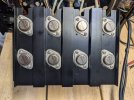
I printed off the AU-919 schematic and ordered a few things from Mouser to use in re-mounting the various power transistors in the unit. I unmounted the F2837 Driver board and Heat Sink. Here is a picture of all the original Sansui output transistors. I will remove and test them tonight and hopefully they will all good...... fingers-crossed!

I have 2 spare NMA1012 transistors so if one or two of them are bad I have an alternative. They have an HFE of 50 and 58. Stay tuned.......:angel:


Installed outputs:

PXL_20251108_225604680.jpg

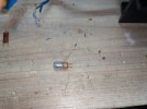
Potential Spares, Not sure what the 840 VS 91Y designation implies........

PXL_20251106_174528156.jpg
 
Tonight I removed and tested all of the ourginal output transistors and am very pleased to report they all tested good!!!:jump:

The hFE values range from 26 to 87. I labeled the heat sink and the transistors I removed and plan on installing the outputs in the same positions they were originally.

The heat sink assembly/ Driver board came out reasonably easily, just had to unsolder the RED/Blue main power lines to gain access. I will think about installing the "sacrificial" Onsemi components in the meantime while I refurbish the driver board.......

Time for a :beerchug:
 
Now that I have the F2387 driver board out I am looking at the F2835 Head amp board and am thinking that with the 2387 driver board and the heat sink out of the way access to the F2835 board seems easier and it might make sense to work on that board at this time. It would break the normal rules of one board, test, then the next board but installing the F2387 and heat sink assembly looks like it will make subsequently accessing the F2835 head amp a bit of a challenge............

Thoughts please!
 
Potential Spares, Not sure what the 840 VS 91Y designation implies........
Once upon a time it was useful information - now its just 'date codes' or 'batch numbers' that we don't understand. However it's nice to see that the originals all have the same 'code' on them, meaning that very likely they really are the 'original' transistors. Your job is to try and keep them that way, by not making any mistakes, If you don't have a DBT (Dim Bulb Tester), I suggest you make one, and learn how to use it effectively before proceeding. :)
 
Last edited:
I removed the F2837 board today and am took a look at the glue situation. There are a few components affected but not too bad, not nearly as fad as the AU-717 I worked on previously. I will start cleaning and replacing components tomorrow. Here is a picture of the board as it is now:

PXL_20251109_222533264.jpg
 
I removed the 470UF 63V capacitors C01-C04 from the driver board as these had the largest volume of Sansui glue around them and I wanted to deal with that up front. There was not any corrosion evident on two of the caps but there was some evident on the two others.

PXL_20251110_012232309.jpg


In the other restorations I have reviewed C39-C42 were 33pF Black Flag caps. In this unit they look like they are foil caps.

Here is a pictyure of one of them removed from the board:

PXL_20251110_013517935.jpg


I guess this may be a later version of the board. Since I have the parts I will replace them anyway.
 
I removed the 470UF 63V capacitors C01-C04 from the driver board as these had the largest volume of Sansui glue around them and I wanted to deal with that up front. There was not any corrosion evident on two of the caps but there was some evident on the two others.

View attachment 3631103


In the other restorations I have reviewed C39-C42 were 33pF Black Flag caps. In this unit they look like they are foil caps.

Here is a pictyure of one of them removed from the board:

View attachment 3631102


I guess this may be a later version of the board. Since I have the parts I will replace them anyway.
Seems like at some point Sansui figured out the black Flags were a problem?

Those are polystyrene caps. They are very good caps and typically don't often fail. I usually leave them alone.

However they don't usually tolerate soldering and desoldering heat well. Potential extreme value changes.
 
I removed the 470UF 63V capacitors C01-C04 from the driver board as these had the largest volume of Sansui glue around them and I wanted to deal with that up front. There was not any corrosion evident on two of the caps but there was some evident on the two others.

View attachment 3631103


In the other restorations I have reviewed C39-C42 were 33pF Black Flag caps. In this unit they look like they are foil caps.

Here is a pictyure of one of them removed from the board:

View attachment 3631102


I guess this may be a later version of the board. Since I have the parts I will replace them anyway.

You might consider a sharpened chopstick and acetone for the glue removal - no PCB scratches.
 
That capacitor you have removed and pictured (post #11) isn't a Black Flag - it is a very nice Noble polystyrene capacitor which is sensitive to overheating when it is being soldered, be gentle with them they are NLA. ;)

Black Flags are black and spookily look like flags!

Somehow I missed mrk229's post above :p - the advice does bear being said twice though. :angel:
 
Last edited:
You might consider a sharpened chopstick and acetone for the glue removal - no PCB scratches.
After removing the components from the glue area , I put over the glue a thin piece of cotton and I wet it with acetone , I leave it there for about 20min (re-wet it as the acetone will evaporate) .
After 20min I remove the cotton and I can remover the glue simply with my finger, repeat the procedure if the glue is thick.
No tools required.
 
I removed the 470UF 63V capacitors C01-C04 from the driver board as these had the largest volume of Sansui glue around them and I wanted to deal with that up front. There was not any corrosion evident on two of the caps but there was some evident on the two others.

View attachment 3631103


In the other restorations I have reviewed C39-C42 were 33pF Black Flag caps. In this unit they look like they are foil caps.

Here is a pictyure of one of them removed from the board:

View attachment 3631102


I guess this may be a later version of the board. Since I have the parts I will replace them anyway.
As mentioned above they hardly fail but they do . I have been through several restorations and I have found only 2 of them failed . Problem is that until I figure out that the problem was coming from those capacitors , I have spend infinite time checking transistors and resistors for troubleshooting…. I’m still debating if they should stay or go in a restoration .
I can not find a video that I show in YouTube from a sound engineering conference ( big names involved) that they claimed as for the moment the best (technically) resistors for sound are thin films and foils and capacitors are MLCC/C0G (NPO).
Meaning that there are options for replacement.
 
After removing the components from the glue area , I put over the glue a thin piece of cotton and I wet it with acetone , I leave it there for about 20min (re-wet it as the acetone will evaporate) .
After 20min I remove the cotton and I can remover the glue simply with my finger, repeat the procedure if the glue is thick.
No tools required.

Thank You, I have one more section on the driver board to clean today. I will give your technique a try!
 
After removing the components from the glue area , I put over the glue a thin piece of cotton and I wet it with acetone , I leave it there for about 20min (re-wet it as the acetone will evaporate) .
After 20min I remove the cotton and I can remover the glue simply with my finger, repeat the procedure if the glue is thick.
No tools required.

I agree completely with this. And I should have clarified. I use pieces of microfiber cloth and soak first. And it seem like no matter how much soaking, there is always a stubborn piece of glue that won't release. That's where the sharpened chopstick comes into play.

My AU-317 restoration -
Screenshot 2025-11-11 at 6.56.34 AM.png
 
I have completed the restoration of the 2385 Driver board. First, my thanks to Sui-Yogi and JimEGR for the chopstix and Acetone 20 minute soak recommendations. I applied this technique to the last section of the board and as suggested almost all of the significant glue deposits came right off! I wish I had known this technique back when I was servicing the AU-717, it would have saved me many hours of work.

Aside from C39-C42 not being Black Flags I also observed that C51 and C52 were no longer .47uF but were now 1 uF units so I replaced them with 1 uF film caps. I also replaced two resistors that were affected by the glue, they measured at the proper value but I replaced them as they were pretty heavily affected by the glue.

Here is a picture of the finished board:


PXL_20251113_140719657.jpg

On other restoration threads I read the driver transistors were not removed and re-seated. I am thinking I will replace the mica/paste with silpads as the silicine grease I saw on the main heat sink was kind of dry.

Thoughts?
 
Back
Top Bottom