• The move to the new server is done. There are some software and database maintenance updates in process. This has us passing the hat around to help out. We appreciate any donations. Seriously, even a dollar helps. The payment page may be found here - https://www.audiokarma.org/support.html

Beginning my Sansui AU-919 restoration

I have completed the restoration of the 2385 Driver board. First, my thanks to Sui-Yogi and JimEGR for the chopstix and Acetone 20 minute soak recommendations. I applied this technique to the last section of the board and as suggested almost all of the significant glue deposits came right off! I wish I had known this technique back when I was servicing the AU-717, it would have saved me many hours of work.

Aside from C39-C42 not being Black Flags I also observed that C51 and C52 were no longer .47uF but were now 1 uF units so I replaced them with 1 uF film caps. I also replaced two resistors that were affected by the glue, they measured at the proper value but I replaced them as they were pretty heavily affected by the glue.

Here is a picture of the finished board:


View attachment 3633186

On other restoration threads I read the driver transistors were not removed and re-seated. I am thinking I will replace the mica/paste with silpads as the silicine grease I saw on the main heat sink was kind of dry.

Thoughts?
Looking good :thumbsup: I use a lot of sil-pads, I think it is smart to buy the high quality ones like Bergquist.

Some of the no name silicone generics from the bay or big A seem to be pretty flimsy and it seems like a sharp burr or the sharp corner of a TO-220 device could punch through them easily.
 
On other restoration threads I read the driver transistors were not removed and re-seated. I am thinking I will replace the mica/paste with silpads as the silicine grease I saw on the main heat sink was kind of dry.

Thoughts?

Yes to this.

And looking good!

(edit - missed Mrk's post as I was typing)
 
Today I removed and re-installed the driver transistors. I tested them while they were out and confirmed that they were ok. I was a bit surprised that there was no insulating washer/ring between the mounting screw and the heat sink. Sansui relied on the mounting tabs on the heat sink and the circuit board to position it to avoid contact with the collector screw passing through the assembly. I re-installed the transistors and conformed there was no contact with the heat sink and the collector screw. All is well but was still surprised by the mechanical arrangement.

Here are some pictures of the completed board and of the heat sink before one of the drivers was installed illustrating my concern. Pardon the blurry image....

Next big desision is weather to install "sacrificail" outputs or to install the original Sansui outputs before proceeding further.

PXL_20251113_193852361.jpg


Finished board with driver cilpads.


PXL_20251113_233013414.jpg
 
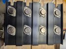
After thinking about it probably too much I decided to re-install the original Sansui output transistors in the unit. Since I have replaced all of the black flag caps on the F2387 board I feel that this is ok at this point. The next board I will do is the F2835 board which has a bunch of black flag caps on it as well. Here is a picture of the heat sink with the original output transistors installed with silpads. I confirmed with an ohmmeter that the transistor cases were isolated from the heat sink.


PXL_20251116_010909693.jpg
 
Don't forget the use of a DBT every time you do an update, i.e. changing components, disconnecting/re-connecting wiring and so on. Particularly important now you have decided not to install sacrificial Output Transistors. ;)
 
Last edited:
Today I worked on removing the 2835 board. The nomenclature used to describe this board in the documents and threads is a bit confusing. The AU-919 service manual call it the Equalizer amp circuit board while the various threads call it the head amp board.

Anyway after reading other threads and staring at all of the connecting wires and ribbon cables I decided to unsolder the two grey ribbon cables connected to the F2834 input board as well as a few other wires that were in the way. I removed some of the wire wraps on the wiring harness and now have enough slack to be able to awap out components. To clean off the glue I will have to flip the chassis over so the board can rest firmly while I soak and remove the glue with the 20 minute acetone technique. Time permitting, I will start this process tomorrow.

Here are a few pictures of the 2835 board after I removed it:

PXL_20251119_005244885.jpg

PXL_20251119_005323612.jpg

Pardon the blurry top, I was hoping to be able to remove the bracket/heat sink to provide a bit more manuverability but it seems that the Sansui folks used that same lovely glue to glue the bracket/heat sink to the circuit board. I am tempted to attempt to remove it but fear the possibility of damaging the transistors or the board itself.

PXL_20251119_010714240.jpg

You can see the blue masking tape labels I placed on the leads to ensure I return them to the appropriate connection points on the board when I re-assemble things/
 
I did a bit more work on the 2835 board. I removed the four 330MF caps that had the largest quanty of Glue. Here is a picture of the board after I detached six additional connections to gain better access. I soaked one of the locations with Acetone-saturated paper towels for 20+ minutes. The results were excellent, I will post more pictures tomorrow as I have an acetone-induced headacle right now. A bit of work ahead but I am confident things will go well with a bit of patience on my part.


PXL_20251120_013424331.jpg
 
I finished the acetone/chopsitck gloe removal process and things worked out pretty well. Here is a picture of the glue end of the board.

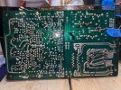
PXL_20251121_171446545.jpg


Here is a picture after I replaced the capacitors and several resistors that were contaminated with the glue. They measured to spec but I replaced them anyway to eliminate and potential future issues.


PXL_20251121_205352770.jpg


I have a lot more caps to replace on this board and several zener diodes. I will work on that tonight after the garage cools down a bit!
 
If you have good desoldering tools (specifically a vacuum desoldering gun) it may be worth to desolder and clean all the wafers of the rotary switches. I have not done it in mine, and I am begining to regret it. Also, there are some recommended modifications suggested (Kohune moddification perhaps??) for this board as well (I believe @Hyperion has experience with them, so hopefully he will correct me If I am wrong). Anyways, you are doing a great job at restoring your amplifier.
 
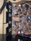
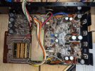
After a holiday hiatus I finished refurbishing the 2835 board and I re-installed it in the Chassis. I am glad I tagged all the leads I unsolderd and took a lot of pictures as putting everything back in place was interesting but ultimately went well. Here is a picture of the 2835 board re-installed. I have not re-wrapped the wiring harness in the event I may have to access the board going forward.


PXL_20251129_031811626.jpg
 

Attachments

  • PXL_20251129_031811626.jpg
    PXL_20251129_031811626.jpg
    131.4 KB · Views: 6
I am debating weather I should re-stuff the main filter capacitors, using this PC board to replace them without the labor-intensive process of re-stuffing or just to leave well enough alone. I recently purchased a FNIRSI® LC1020E High Precision Handheld Digital Bridge LCR ESR Tester and so far I am pretty impressed with it. I read in another post that I could use it to determine if the four main caps were still within spec. Quote from the post:

" Also, the four oval 15000uF filter caps measured between 12060uF and 12500uF with an ESR between .06Ω and .09Ω. This is just above the low end of acceptable"

Sorry, I forget the originator of the post so can't acknowledge them. I plan on making the cap replacement decision as the last step in my restoration process unless one or more of them are wildly out of spec.

All input appreciated!

Sansui main capacitor PCB Board.jpg
 
Today I removed the 2845 main power board from the AU-919. Lots of connections to remove and label but overall not too horifying. There is quite a lot of glue on this board so I guess tomorrow I will be doing the acetone soak and chopstick scrape quite a lot. It looks like several resistors may have been affected by the glue. Guess I will fine out more tomorrow when I soak and scrape.........

Here are pictures of the board before and after I removed it.


PXL_20251130_005104349.jpg

PXL_20251130_040117517.jpg
 
The first thing today I measured the capacitance and ESR of the four main filter capacitors to see how things looked.

They measured at:

#1 13,000 UF ESR .0059 ohm
#2 13,270 UF ESR .0059 ohm
#3 13,200 UF ESR .0057 ohm
#4 12,600 UF ESR .0054 ohm

It looks to me I can proceed with the restoration with the original main filter caps in place. My plan is to get the AU-919 working properly and then decide on wether to re-stuff or use the boards I mentioned above to replace the main filters. In the meantime I have plenty of Sansui glue to deal with!
 
I removed all of the capacitors from the 2845 board and the amount of glue Sansui used is quite impressive. I well replace several resistors affected by the glue. The 2sd357 /2sb527 have some blackening on their leads so I will remove and clean/test them. I was thinking of substituting mje15032/33 as potential replacements. Some threads caution against this but they are referring to situations where the 2sd357 /2sb527 are being used in driver circuits. I am assuming that as regulators the mje15032/33 pair should be fine.


PXL_20251130_202840576.jpg
 
Today I finished cleaning all of the Sansui glue off of the 2845 board. It was more of a project than I thought it would be even with the acetone soak/chopstick scrape technique. After the cleaning I removed and tested the 2sd357 and 2sb527 transistors and they all tested good so I cleaned their leads and re-installed them. I replaced all of the resistors that were affected by the Sansui glue and replaced all the electrolytic caps that were on the board. Here is a picture of the completed board. Tomorrow in the light of day I will examine the board for any potentially poor solder connections and clean off any residual rosin etc. from the circuit side and then re-install it in the Au-919.


PXL_20251202_013754578.jpg
 
Today I carefully inspected the 2845 board for any potential issues before re-installing it in the AU-919. I carefully went through the maze of wires that I have to re-connect to the board before it is mounted and after it is mounted. I dressed the leads and reviewed the pictures of the board I took before and during it's removal from the chassis. I am pretty comfortable with the sequence of events that I must follow before I re-install the board.

While doing all of this I thought it might be prudent to work on the 2844 pre-amp power supply since it was easier to access with the 2845 board removed. It took me a while to figure out where the two-faced tape securing the board was after removing the remaining mounting screw. Once I realized where it was I was able to pry the two bracket pieced apart and pop the 2844 off it's plastic mount pins. Access to the 2844 was quite easy adter removing the three push-on connectors. I changed all of the capacitors and the 24V Zener diode and then re-installed the 2844 back in the chassis. Once the tape mystery was solved things were pretty straightforward. I confirmed that the silk-screened polarity for C07 and C08 are incorrect as observed my others that came before me and installed their replacements correctly.

Here is a picture of the 2844 installed back in the chassis.


PXL_20251203_025005426.jpg


Tomorrow, time permitting I will re-install the 2845 board back in the chassis and re-connect everything as it was before.
 
Today I re-installed the 2845 board back into the AU-919 chassis. Things went pretty well thoufg I wish I had a higher wattage soldering gun to solder all of the power connections in the main power supply. I meant to mention that when I removed the 2845 board from the unit I noticed that the screws that connected the board to the oval capacitors were not firmly tightened. They were not loose per se but definitely not as tight as they should have been. not sure why or if it matters but they are firmly tightened to the point where the lock washers are firmly engaged.

Here is a picture of the board after I installed it. I have not re-wrapped the wiring harness in case I have to remove the board again.

PXL_20251203_204337671.jpg


I have not powered up the AU-919 since I started the restoration. I plan on restoring the protection board next and then doing an initial test to see if the amp comes out of protection. Wish me luck!
 
I just came back in from the garage after trying to get access to the protection board. I removed the five back panel screws and the four screws securing the protection board and rectifier circuit board. The boards move now but it looks like I will have to unsolder the speaker connections and probably a lot of other interconnects to get access to the protection board so I can work on it.

I am asking you experienced hands with the AU-919 to provide some insight as to what needs to be done to free up the protection board. I want to be sure that I am not missing something obvious that will facilitate servicing this board.

Here is a picture of the edge of the board with the speaker terminal wires and the grey/white twisted pair going off to another part of the receiver. Some of the connecting wires might have some slack if I undo the wiring harness ties which will give me a bit more room to maneuver. I can carefully label and unsolder the speaker leads and the other leads which appear to constrain access to the board for servicing. I just would like come confirmation that this is the approach that others that came before me took. Most of the threads detail component selection for replacing existing components but do not provider insight into accessing the boards being serviced.

Any help would be appreciated as this board and the others mounted on the rear chassis look difficult to acess unless I am missing something.......

Thanks,

Rich

PXL_20251204_005536879.jpg
 
It’s been a while since I restored my AU-907Limited but I do remember that the wise move is to remove the back panel.

Unscrew the feet from the bottom cover and screw them directly to the cassis with out the bottom cover so the amp stays elevated.

You will need to cut of the power/Switch/wires coming in from the plug and unsolder the GRN (turntable)wire that goes to the RCA pcb. After, simply take a lot of pictures and mark what you unsolder until you have the back plate free from the chassis.

Extra careful with the speakers wires , better cut off rather unsolder as you might lift the traces .

If you need pictures I can find some and forward it here .

Good luck!
 
Back
Top Bottom